
Logitech Momo 900-degree mod
If you own this Racing wheel. You know that it comes with only 240 degrees of steering. Apparently, there is a mod that exists for this wheel. However, I do have to stress that it is pretty difficult to achieve and is a time-consuming undertaking. This also does some modifications to the wheel at which point there is no going back to stock configuration. Keeping this in mind if you are willing to try this and aren’t afraid of breaking something then it could turn out into an interesting project. I cannot hold any responsibility if you damage your device.
The solution
So I noticed this on Thingiverse when searching for some 3D printer parts and noticed a 900-degree mod for the wheel. I decided to dust off the thing and attempt this since it was already stored in my closet. In my attempt to find some tutorials online, it seems this mod originates from Russian forums like VKontakte. So much of what I found I needed to Google translate to make sense of it. I’ll leave a link to it if you fancy digging around the posts for information. It seems to be pretty active and new updates to the mod seem to come out still.
https://vk.com/momo_mods
This led me to some videos on YouTube that go into better detail on how this mod is performed. To start off before you attempt to begin this do know that this requires either having a 3D printer or to 3D print parts from a store, etc. The video I used as a reference is the one below if you want to check it out.

It doesn’t use the exact same parts I used but it’s a good reference on how the wheel should be assembled.
The video below would be close to what I did with the ring fittings on the wheel.
I would advise you to turn on at least auto-generated captions in your preferred language to better understand what is going on.
The Vkontakte site would be your primary source of information. This is where the adaptors and 3D print files are available as schematics or documentation. But since everything is in Russian language you will need to translate it.
Required stuff:
Parts for 3D printing. The original files are still up on the Google Drive that is hosting them so you can get them from there:
https://drive.google.com/file/d/1xu7rnIPKdUT_53sxBjWyr_dKZLop4v6J/view
Adding a Virus Total scan just in case:
https://www.virustotal.com/gui/file/ef6166bfbcca0c47edf02e5f6be6e0ad7a3648c617cf85feddae6c4a1d571a21/detection
From the available parts, I am uploading the ones I used which come from the same file as above:
A Virus Total report can be found for this as well:
https://www.virustotal.com/gui/file/2b4bbb6782fdb4bfc8e7ba76d1e0c004cfb690060f6581fff429faf9a0c69c8c?nocache=1
You will need a GT2 6mm width and 166mm length timing belt. An example of such a belt can be found here:
https://www.aliexpress.com/item/4000307124092.html?spm=a2g0o.order_list.order_list_main.280.24221802Noa434
Grease or Lubricant for the plastic parts like in the example:
https://www.amazon.com/Super-Lube-Silicone-Lubricating-Translucent/dp/B08M8NYHLW
Official Logitech Momo drivers(If you don’t have them already):
https://support.logi.com/hc/en-au/articles/360024843413–Downloads-Logitech-MOMO-Racing-Force-Feedback-Wheel
The mod itself
So this of course firstly requires to dissemble the wheel. For that, you will need to open the shell casing. On the bottom of the wheel, you are going to have Philips head screws.
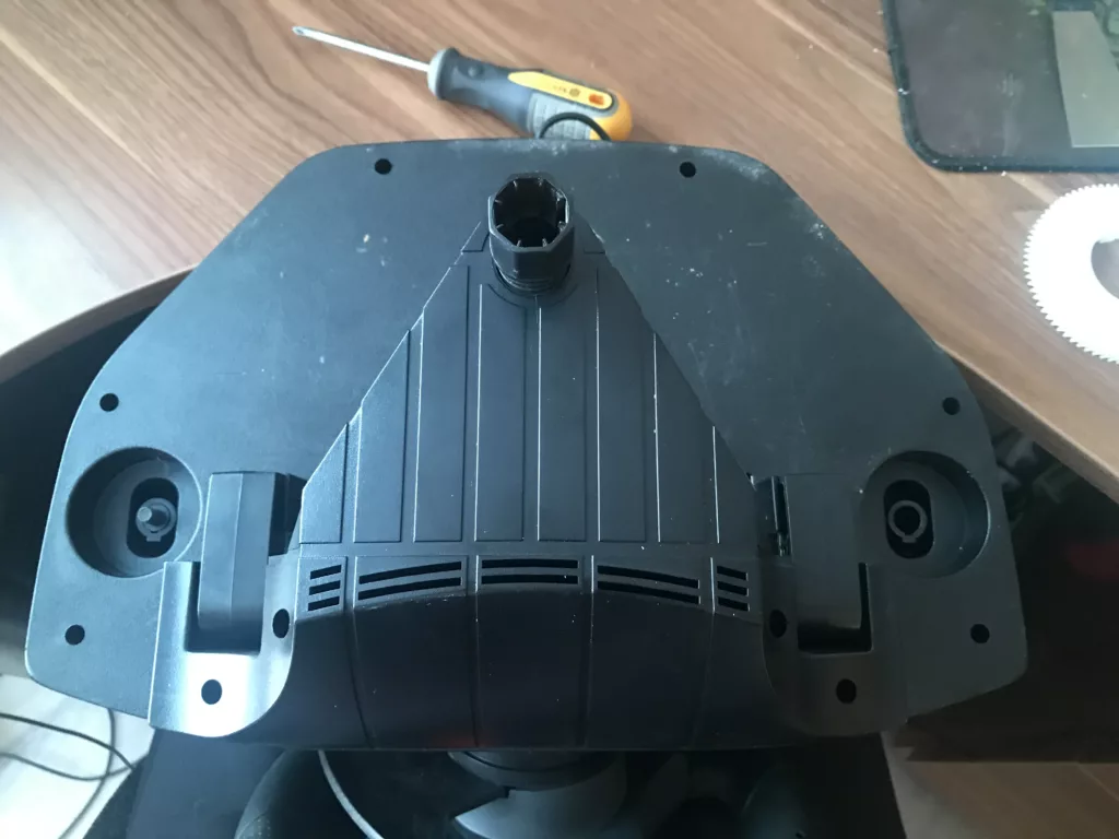
You can start by removing the clamp assembly to separate it from the bottom and there will be a few more screws underneath.
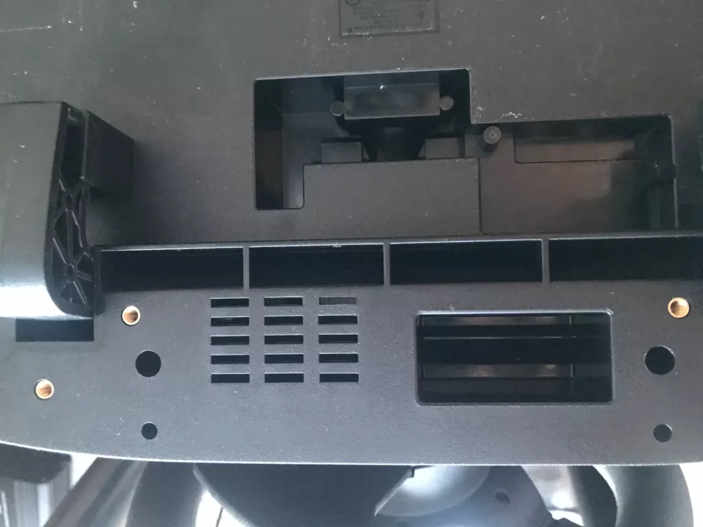
The gear shifter has a nut screw on the bottom. To remove the top cover you will need to unscrew it to release the shifter. The shifter itself pulls out from the top. When removing the casing keep the wheel in the upright position as the shifter inside is held in place with a pad that has springs and if you try to open it upside down the parts are loose and will fall out.
Once the cover is off you will have access to the internals. We can start by unscrewing the screws that hold the steering wheel in place.
The cable that comes out of the end of the steering wheel needs to be disconnected from the connector nearby. You can lift out the wheel afterward.
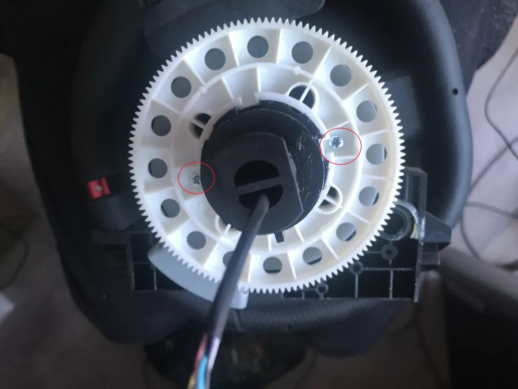
Remove the two screws and remove the plastic gear. You will reveal 4 holes underneath that we need to unscrew.
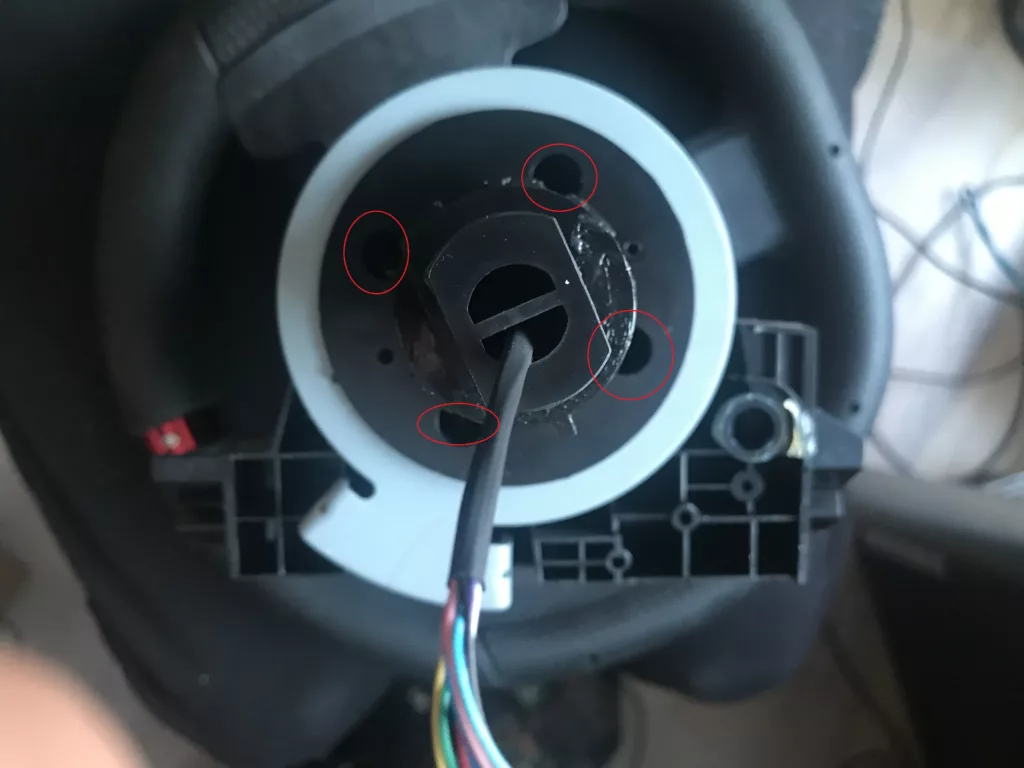
Now the problem here is we need to feed out the wire through the hole to remove this unscrewed base. Two ways to go about this. Either cut/break the middle plastic piece in the hole that the wire comes out of or unplug the wires from the connector.
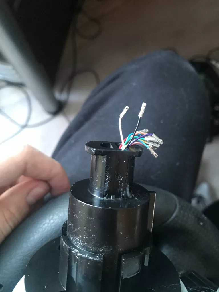
I personally didn’t want to start cutting where it is unnecessary so I pushed in all the pins on the connector and pulled them out one by one. Take a photo or make a diagram of which wire should go into which connector pin as you will need to reassemble this later.
The steering wheel can be put to the side for now.
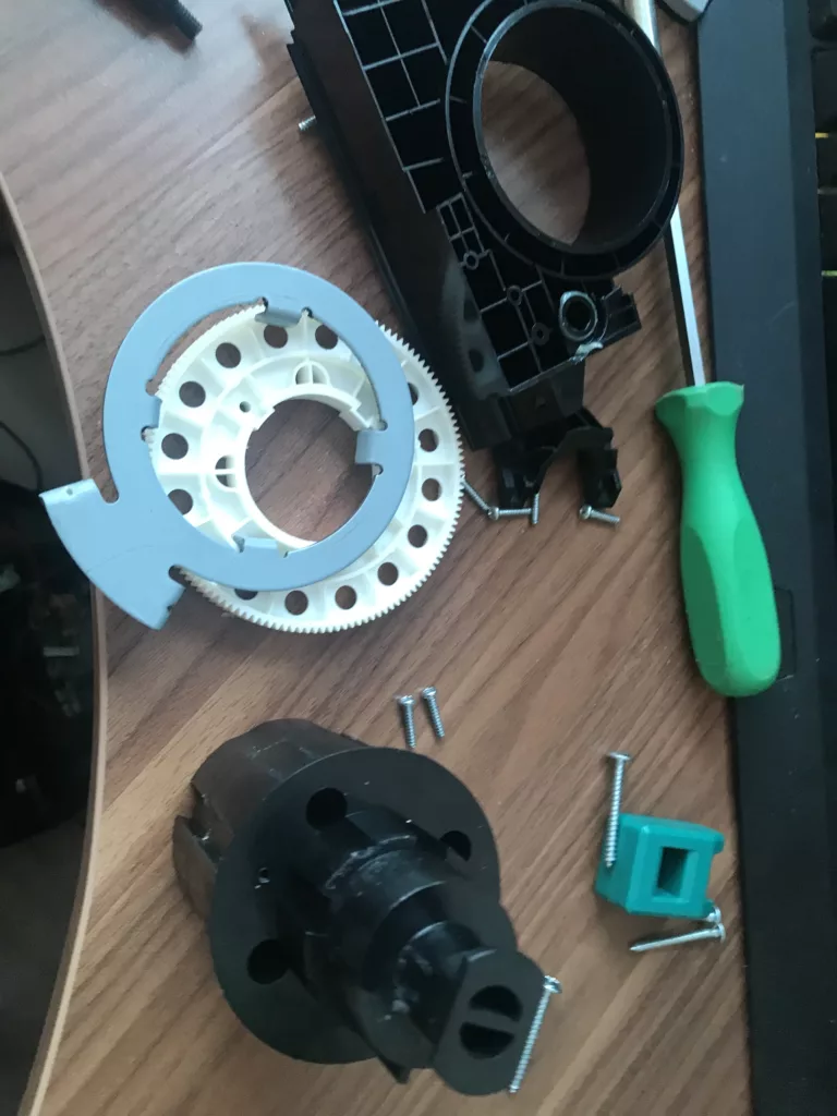
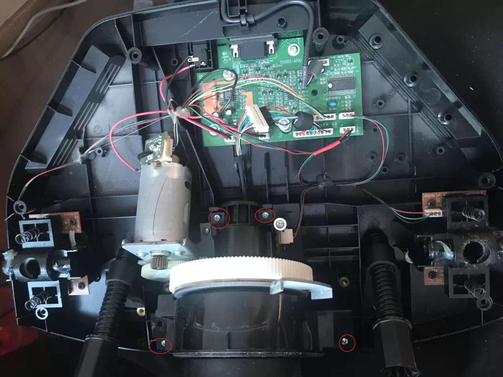
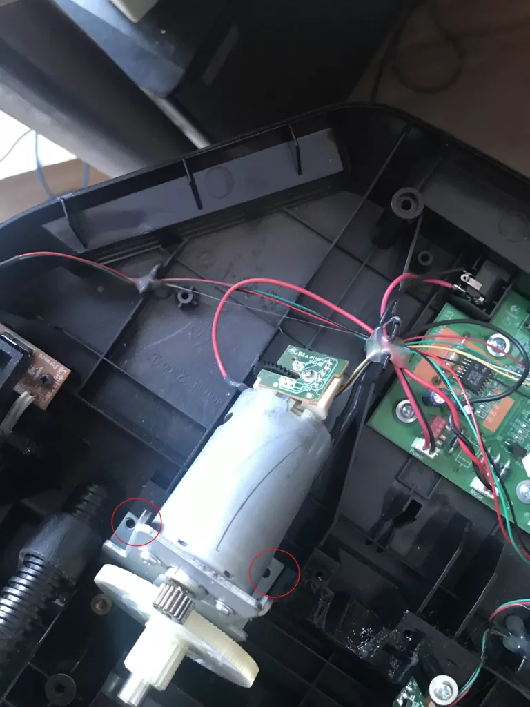
You should now have these parts separated. Next, we will remove the encoder and motor. Remove the highlighted screws and the motor can be lifted out.
The other end of the motor has the encoder attached which we will need to disassemble. You can also remove the front white plastic gear of the motor.
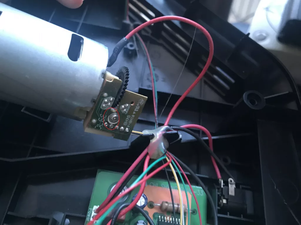
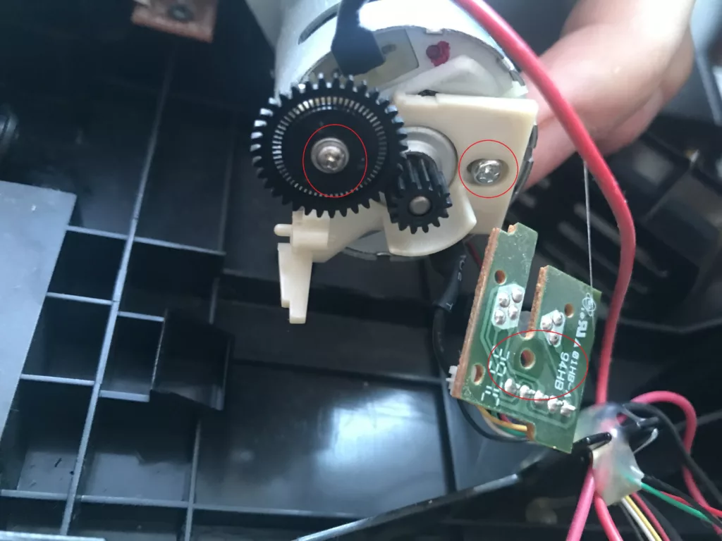
There is a screw for the board. and a few more for the encoder gear and assembly.
We can assemble the new encoder motor now if you have the parts ready and printed. The best is to view the assembly video provided on how these go together. It should be straightforward.
Pars for this are:
Body-1_v2.stl / Body-2.stl / Shaft.stl / Helical-Gear-21_(900).stl
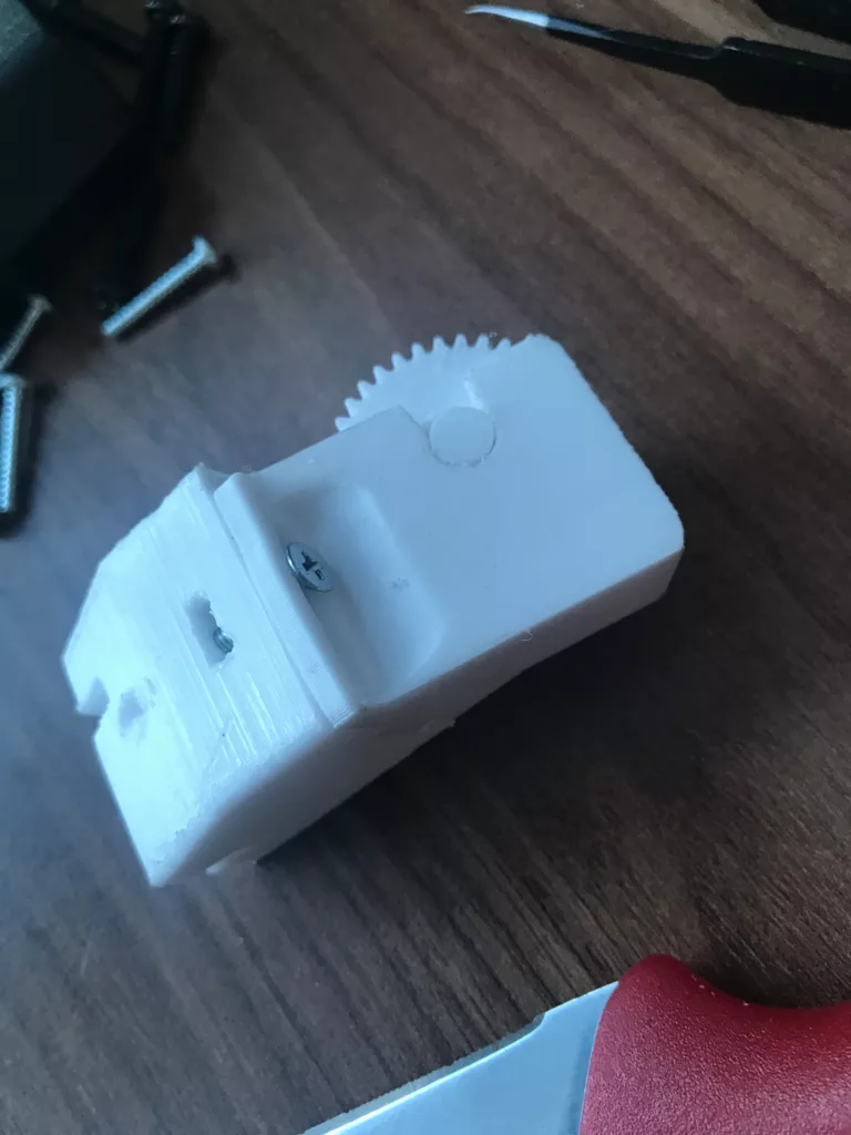
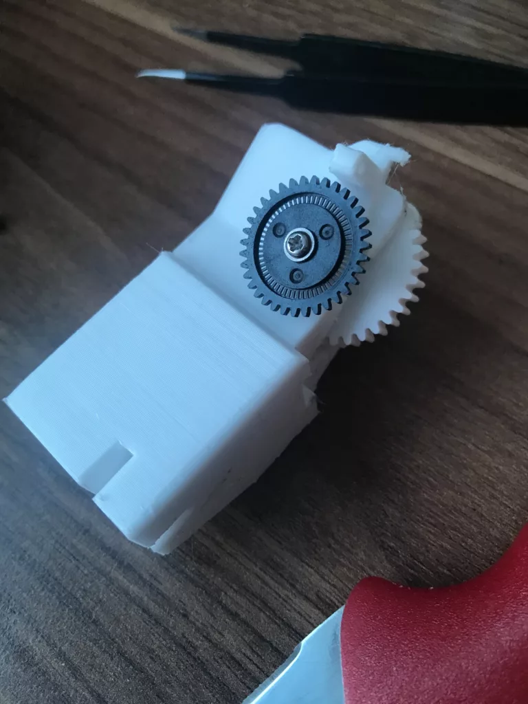
All parts are 3D printed except for the screw that prevents from the parts sliding and the Encoder gear that we removed previously. There is a wide notch in place where the screw goes for adjustment. This is just to get the spacing right so that the gears touch and turn when operated once assembled.
There is a screw hole to attach the encoder board so that it sits nicely. The bottom of the assembly has grooves in place for fitting on the bottom of the wheelbase. This will go next to the wheel assembly instead of the motor we took it off from. The placement can be done later when the steering wheel is back in place as it may need adjustments.
We can continue now with the motor.
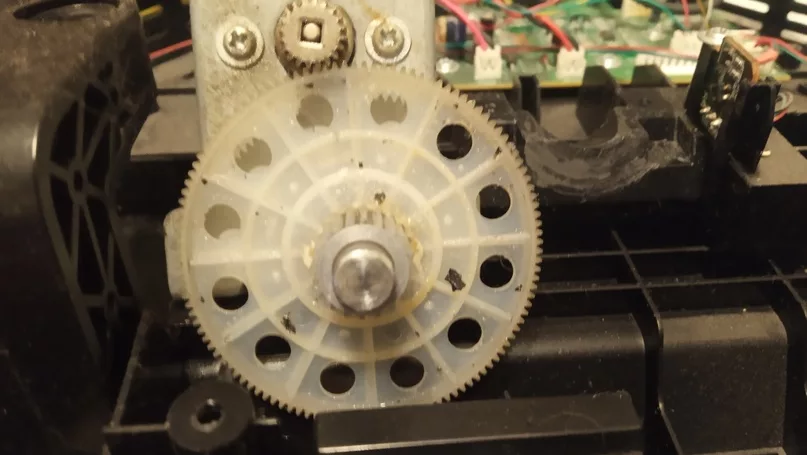
So if you haven’t removed the large plastic gear you can do so now. Loosen the two screws near the small metal gear.
Now we can place the other 3D printed parts here.
Parts needed:
Pulley-23.stl / Pulley-Gear-67_Nylon.stl / Depending on which is better for you ( Ring_0.8mm.stl OR Ring_1.5mm_(900_600).stl OR Ring_2mm.STL)
The different-sized rings are there for a reason. Is that the belt needs to be straight between the two gears when attached so that there is sideways pulling. The different sizes of the rings help get that straightened out so you will need to test which fits best.
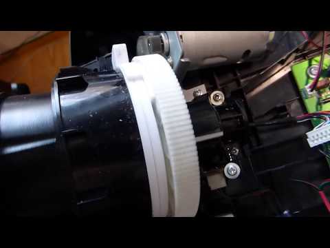
The Pulley-Gear-67_Nylon.stl goes on top of one of the rings placed. The Pulley-23 is slid on the metal gear. If it’s a hard fit a rubber mallet helps with light taps so that it slides in flush with the gear. Once both gears are in place you must put the belt on. The belt is quite tight so some force should be applied. I prefer to add the belt starting from the small gear and work my way by placing the belt on the large gear by rotating it and pushing it on as it moves. Once on check that it is flush in between the gears and it should not be too tight as it needs to have good tension but not too loose but not overly tight as this will depend on the force feedback features you will receive once using the wheel. There are many files in the archive and you can go about this your own way. It is even possible to do the mod without the belt and use the gears themselves or print different ones. This has different effects mainly in how the wheels react and the force feedback features. So this is on personal preference on how to approach this. The YouTube user SeGord has many videos on different modifications and goes to great lengths to modify this model. Tighten the two screws back down next to the small gear.
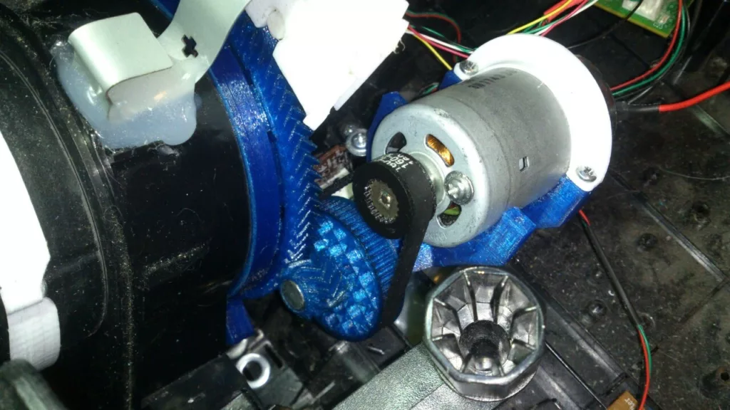
Based on my mod it should look like this. Disregard the colors as I couldn’t find a decent picture and pulled one from someone else’s but it should look the same. Both of the printed gears have little walls around them preventing the belt from falling out which is a nice feature.
Back to the wheel one of the plastic parts we removed that the round base goes into we need to modify by cutting some of the plastic out as it impedes our 3D printed rings from spinning around when the wheel is turned.
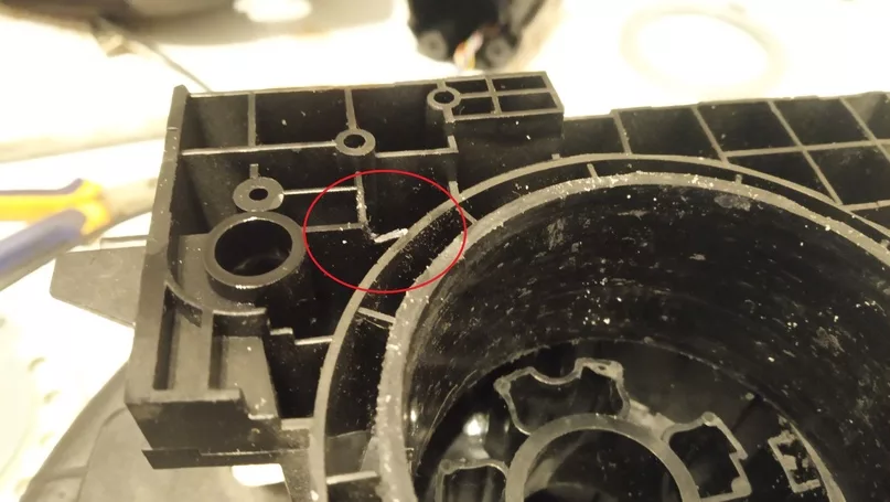
This area needs to be cut out so that the ring once placed on can spin around without hitting it. The other place where we need to modify is close by at the edge.
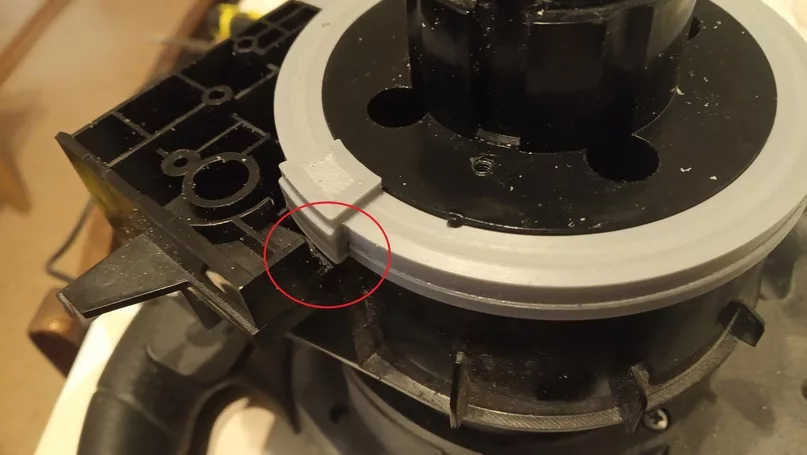
You can add the Ring-1_(900).stl and/or the Ring-2_(900).stl to see if they can rotate around without obstruction.
The two rings go one after the other and the third one Ring-3_(900_600).stl aligns inside of Standard-Gear-130.stl which has two screw holes and the protruded parts on Ring-3_(900_600).stl goes inside of the grooves in Standard-Gear-130.stl. This is best shown at the 6min. mark of the video below.
The Ring-3_(900_600).stl is not used in some of the tutorial videos provided and some do so depends on what you follow as your guide it may differ. You can start reassembling the wheel with all the parts feeding the wire back and attaching the connector if you removed it previously. Don’t forget to use some grease or lubricant for the moving parts as it will help everything glide and move easier.
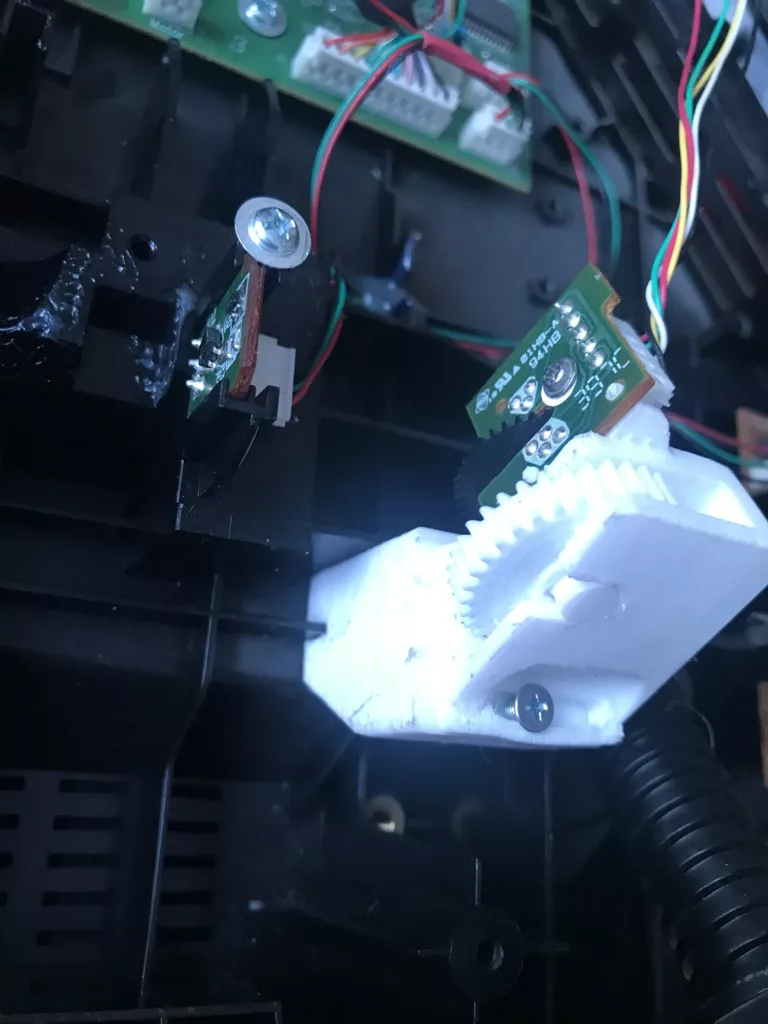
You can go about reassembling all the parts. Since we have the encoder assembly done. The wheelbase assembly was done and the motor was modified with the belt. All can be placed back and reconnected. Do keep in mind that the Standard-Gear-130.stl which is on the wheelbase will need to touch and rotate both Pulley-Gear-67_Nylon.stl on the left side where the motor is. Also the encoder Helical-Gear-21_(900).stl should be spun which now sits on the right side of the wheel.
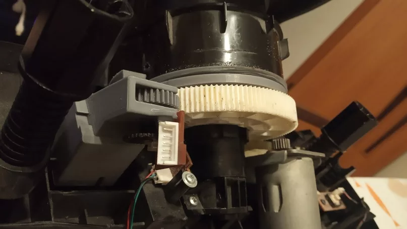
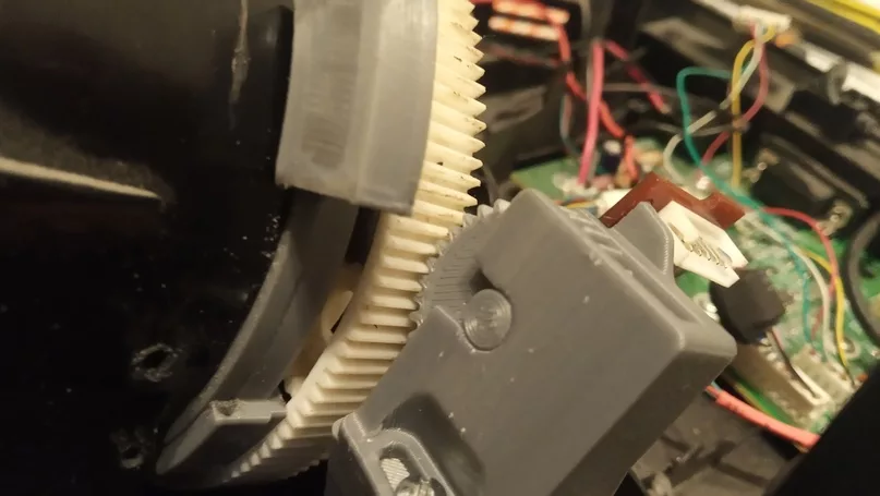
Photos are just for reference to better understand where the encoder now sits and how it should be working.
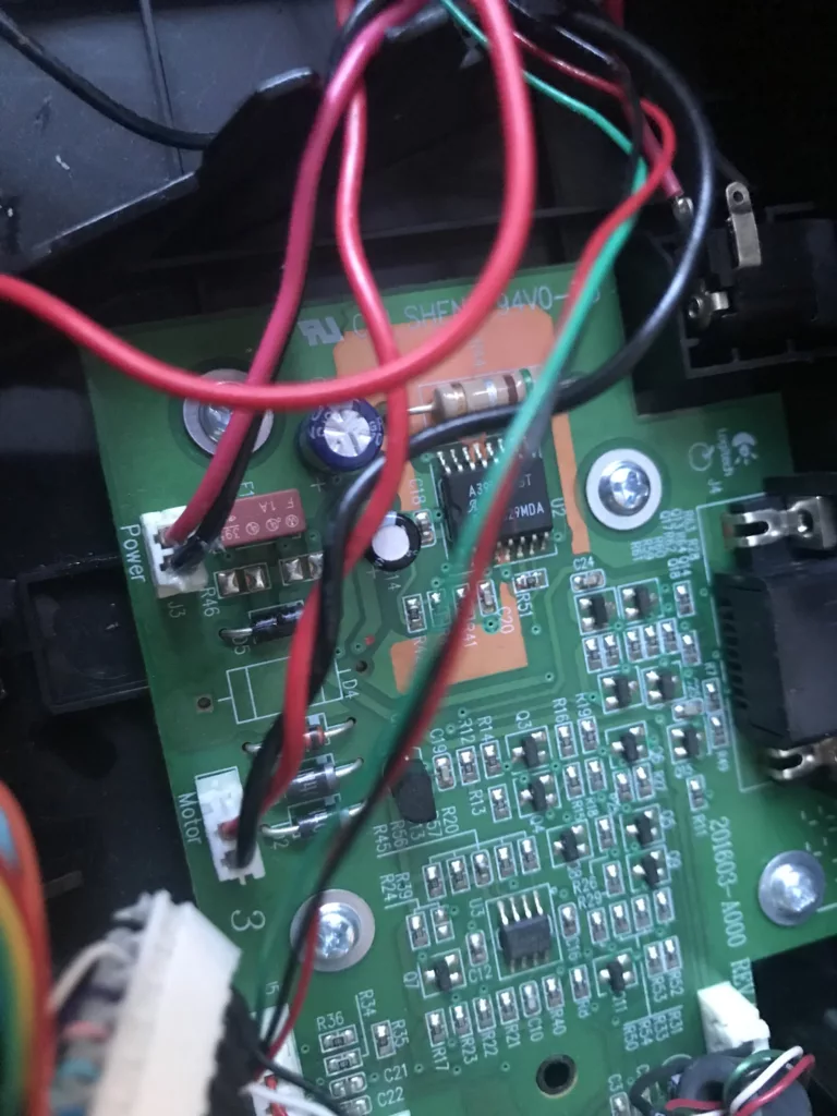
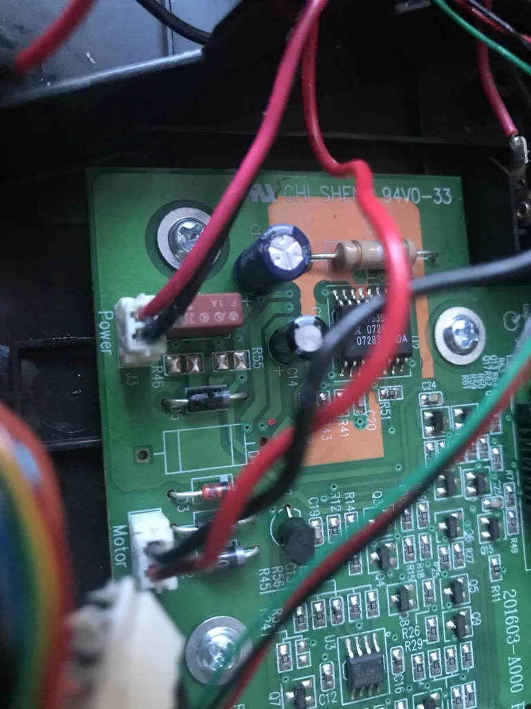
The last thing we need to do which is not mentioned in the video just very briefly shown with no explanation. We need to swap the cables on the motor connecter. So on the mainboard, you will find a connector that is marked as Motor. This connector will have a red and black cable coming into it. Now we need to swap the cables. So the black needs to go where the red goes and vice-versa. If you removed the pins from the wheel connector this is the same thing. Unplug the connector push in the pins of the cables swap them and plug it back in.
At this point, everything can be assembled to the point where we would put the top case on. But we can already test this to see how it works. I would recommend plugging it into your PC to check if everything is working as expected. The software doesn’t know that the wheel is modified so when plugging it in I would suggest setting the wheel straight so that when the initial test runs it doesn’t knock on the sides. There really aren’t any settings as the software will think it turns the same degrees but the encoder is spinning at a different speed so the encoder is sending the same information but you need to turn a lot more. If everything seems right I would recommend booting up a game and seeing how it handles. Most games have some settings that you can probably adjust to change the feeling or the steering but it depends on each game. A short “before and after” of the mod itself.
Conclusion
This mod is quite extensive which requires unrecoverable modifying some parts of the steering wheel. Everything in this mod is just hardware modifying which also tricks the software. But no coding or software tuning is required. I cannot stress this enough but please perform this at your own risk this is not an easy mod and some modifications and testing will probably be needed to make it work even beyond what this guide or the videos portray. There is barely any support I can provide to this as the mod has too many layers and can be modified even beyond this method. Your best bet would be the guides from the creators I linked on YouTube or researching the VKontakte forums for assistance.
If you are still interested in doing this project. I hope it brings new life to your racing experience.
As always I hope this has helped you out.


Thank you for the tutorial, especially the encoder part, because before seeing your tutorial, I was confused about where to install the encoder mount because there is no mount and on the ring part, you are right, it has to be cut to be able to rotate, no wonder the left side of mine is a little raised. Sorry if it is difficult to understand because I used a translation 😃
Qual seria a correia usada ?
It’s mentioned in the guide. I used a GT2 6mm width and 166mm length belt.
Helical-Gear-21_(900).stl is not adequate, do you have another stl version for standard main gear.
Thanks
Hi,
If you need a different part the original archive of parts can be found here which may contain different versions. The 1.6 version archive is below:
https://drive.google.com/file/d/1xu7rnIPKdUT_53sxBjWyr_dKZLop4v6J/view
After checking I see that there is a newer updated version 1.8 of the parts files. Might be worthwhile to check this one as well.
https://drive.google.com/file/d/16EpEn5JfGrfV24vm64bPXMuvCnuROyDd/view
Regards