
Sliding Gate control with Tasmota and Home Assistant
If you have an automatic gate system like a sliding one in my case. You may have thought about being able to control it remotely. Of course, remote controls exist but usually, the ones that come with the motor have a short range. Sometimes the gate opens and closes slowly so once you operate it with the remote you are left standing waiting for it to open. So if you want the gate to be already open as you are driving back or for example, you want to let someone in while you are away then home automation is a way to achieve this.
The situation and setup
In my case, I have a sliding gate with a CAME BX708AGS motor. Which works fine with the remote. But as the premise of this post, we want more functionality. So with this in mind, I will at least list some items that will be needed for this to work. Keep in mind this is not a one-size-fits-all-all. Different motors and models may need different solutions as they may have operational or environmental specifics.
If you want an all-in-one solution without much tinkering it may be too difficult for you. There exists a product called Remootio. Which is an easy-to-use solution for most people. Just comes at a premium of 119$ (as of the time of writing). This is something I’ve found while searching for the best setup myself. In theory, it should be possible to integrate it into the home assistant as it has some API documentation. But since I don’t own it I cannot say if it works or not. The reason I am mentioning this is that the Remootio site is kind enough to have a compatibility checker. This is where you put in your gate motor model and see if it’s compatible. The best part is it gives you a wiring diagram. This is what I took to further lay my plan for the integration. You can check it here:
https://www.remootio.com/pages/compatibility
So if I write my model it comes up with the diagram.
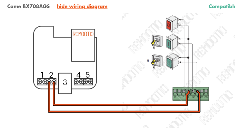
Looks simple enough two wires connected to the corresponding contacts on the mainboard Pin2 and Pin7. Now to figure out what this is I just open the actual manual for my motor which has the details.
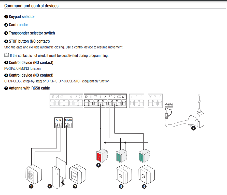
As it states the pins are used to “Stop the gate and exclude automatic closing/Ise a control device to resume movement). And the 7PIN specifically is stated to OPEN-CLOSE (step-by-step) etc..
So this is basically what we want which is great. The manual corresponds to the same thing that the Remootio site told us.
From here we can start laying out the tools we will use.
Prerequisites:
Have an instance of Home Assistant already running. The official page for this can be found here: https://www.home-assistant.io/getting-started/
Your Home Assistant needs to have the following integrations configured:
https://www.home-assistant.io/integrations/mqtt/
https://www.home-assistant.io/integrations/tasmota/
Be ready to install Tasmota on the ESP32 board:
https://tasmota.github.io/docs/Getting-Started/
ESPHome also exists but we won’t delve into that as we are using Tasmota in this case.
This may differ depending on your gate motor and or setup environment. For myself, I chose the ESP32-WROOM-32U with an additional antenna because the gate is some distance away from the house and I need a strong wifi signal for communication.
ESP32-WROOM-32U Aliexpress
Another thing we will need is an AC/DC Buck converter. For this, I chose the LM2596HV. I will provide more detail on why I chose this as with the ESP you may need a different one as it depends on your setup.
LM2596HV Aliexpress
We will also need a 5V 1-channel relay. There are no specifics for this but a relay is required for controlling the gate. I believe there are ESP modules with integrated relays. But I used a separate one. I chose the KY-019.
KY-019 Relay Aliexpress
Optionally you can also get a magnet switch. This can give you status updates for example to let you know if the gate is open or closed but is not required.
Magnet switch Aliexpress
Find yourself a micro USB cable to sacrifice. As in my case, I will connect the Buck converter to the ESP32 with a gutted USB cable.
Have a multimeter on hand as the buck converter needs to be adjusted for the correct voltage.
Some additional tools are a soldering iron, some small screwdrivers, cable strippers, a batch of Dupont cables, and as a bonus having a 3D printer or access to one is optional but a great way to create a sort of storage box for all these components. Once everything is ready we can proceed with the setup
The solution
The following assumes you have the main prerequisites set up as this will mostly focus on the sliding gate automation. First, let’s set up the ESP32 module. Flash the Tasmota firmware using the guide. I personally just used the browser flasher listed in the guide while the ESP32 was connected to my PC via a USB cable. Then it can be accessible with the WiFi connection configured for further configuration. This can be left aside for now as we can prepare the rest.
Going forward to the LM2596HV converter the reason I chose this is that the ESP32 accepts and needs 5V as a power supply. While the CAME motor does not provide such voltage output we need a converter. My model in particular has only pins for power that is 230V or 24V AC as detailed which is not ideal but we can work with this.
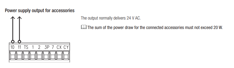
I don’t want to be converting 230V to 5V. So we are using the ones listed above and the LM2596HV works great in this case because it can convert the 24V AC to 5V DC. And Pin10 and 11 are right next to Pins 2 and 7 which is what we will use the relay for.
Using a multimeter I double-checked that the Pins are outputting 24V. Going forward I shut off power to the motor as I don’t want to blow any fuses while I’m working on it.
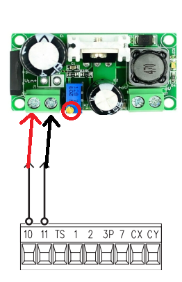
In my case, I connect the two wires to the designated AC contacts on the converter. Using the multimeter attached the ends on the other DC side and while turning the screw ( circled in red) adjust the voltage to 5V. Once that is done. We have the Buck converter ready and can put it aside for now. You can also use a 24V adapter to adjust the power instead of on the motor itself. In my case, I did not have one on hand so I just used the supply from the motor. Additionally, since I am no certified electrician I do not know if it matters but the AC side can take input from 5V to 30V. But I’m not sure if it matters on the input voltage when adjusting the DC output. So if I give it for example 5V will it output 5V whether the input is 5 or 24 volts? Maybe someone more knowledgeable can clear this up in the comments.
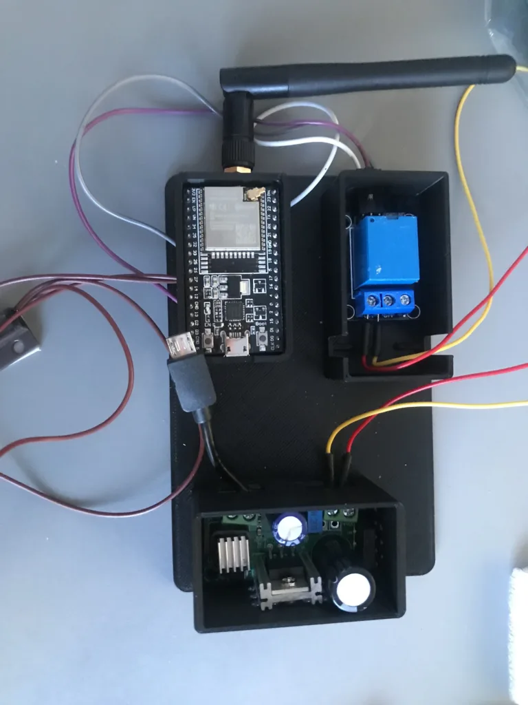
In this case, now we have everything ready to be wired up and configured. I personally first tested this just with the ESP32 and the relay module. But I will leave this finished crude wiring diagram as a reference as to how this should be set up by the end.
What we want to achieve initially is control of the relay. So that when a command is sent the ESP module switches the relay on and off.
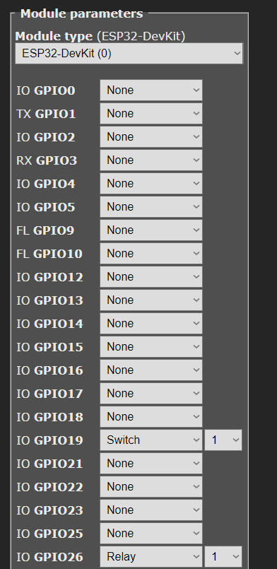
So since we have Tasmota on the board set up. Once plugged in it should be accessible via its IP address. If you didn’t write it down or set a static one I would suggest looking in your router for what IP address was issued or using a program like Angry IP Scanner to scan your network for active devices. Once opened in the browser we can go to Configuration -> Configure Module. Here based on the wiring diagram, we can set up the pins. For GPIO19(OPTIONAL) we can select Switch from the dropdown menu and for GPIO26 we can select Relay. You can then click Save at the bottom.
Once done you can go back to the Main Menu. If the relay is already connected you can test if it’s functioning. The Main menu will have a Toggle button now since we set up a Relay.
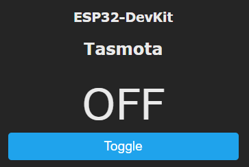
When pressed it should switch from OFF to ON and vice versa. Once the toggle is pressed you should hear an audible click sound from the Relay. Notice that it does not switch back to OFF and remains in the ON state. So you can press Toggle again and it should click again and be OFF. In this case, the basic functionality works but we need it to Toggle ON and OFF within 1 second because our gate is expecting this kind of signal for operation.
For this to happen correctly we need to configure some changes. Go to the Consoles menu and select Console. A terminal will open up so we will apply some options to configure the devices.
In my case, I entered the following for the Relay:backlog setoption0 0; poweronstate 0; switchmode1 1; pulsetime1 10
backlog allows us to use multiple commands in a single line.
https://tasmota.github.io/docs/Commands/#the-power-of-backlogsetoption disables saving of the outputs to the EEPROM memory. This is mainly for safety if, in case of power outages, the board starts up with any of the outputs always in the OFF status.
https://tasmota.github.io/docs/Commands/#setoptions
poweronstate sets the relay status to be OFF when the device powers up. Also for safety in case of outages.
https://tasmota.github.io/docs/PowerOnState/switchmode sets the Relay to the Toggle mode we need for it to function as we intend it to.
https://tasmota.github.io/docs/Buttons-and-Switches/#switchmodepulsetime is a timer for when the relay to wait a set amount for it to switch back off. In this case 1 second.
https://tasmota.github.io/docs/Commands/#control
You can then go back to the main menu and test the Toggle switch to see if it operates as desired. All the commands used are linked to their respective wiki pages and if you need to make changes based on your configuration you can adjust accordingly.
This part is optional but if you wired the magnet sensor then you will need to add some additional arguments to the Console. You can also test the behavior of it and see what is happening in the console. The messages in the console terminal should show the POWER state of the switch going from OFF to ON and vice versa when bringing the magnets closer and or pulling them apart.
For this we would need to create a rule:rule1 on on switch1#state do Publish stat/gate/POWER1 %value% endon
This enables rule1 to use the switch1 state and Publish the topic which you can change to what you decide to set as the Topic in the MQTT settings which we will get to shortly, in my case for naming sake I just named it “gate”. The value field will be either the ON or the OFF statuses.
Afterwards, you can just type rule1 in the terminal it should show you the rule that we just entered. You can read more about the rules in the wiki:
https://tasmota.github.io/docs/Rules/
You can again test by moving the magnets closer/apart to see the changes in the console window. With all of this working, we now have a working solution. The gate should open and close when the relay is toggled. The magnet shows the state when the gate magnet moves away or comes into contact. This is of course only usable through the Tasmota UI. Now we want to make this more pretty and usable by integrating Home Assistant.
The automation
If you followed the prerequisites. You have Home Assistant running, MQTT and Tasmota set up. Since we have our ESP board configured and wired up we want to onboard it for automation. This uses MQTT to communicate between the automation software and the ESP board. If you have read my previous post regarding integrating a hot tub.
https://antanaitis.lt/2023/09/13/home-assistant-hot-tub-integration/
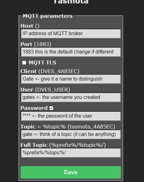
The main thing needed apart from the MQTT integration is a User. I highly suggest creating and not using your main one. It is very simple to do you can check that previous post out. So having the user and the IP address of our MQTT broker. We go back to our ESP Tasmota UI. Go to Configuration -> Configure MQTT.
Here enter your details and hit Save.
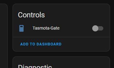
You should then go to the Home Assistant interface if everything is correct the Tasmota integration should be a device. This can be seen under Settings -> Devices & Services -> Tasmota and clicking on Devices. If not then it’s best to troubleshoot through the MQTT broker by checking the logs for any authentication issues. As well as making sure that both devices can communicate with each other on the network.
In my case integration goes smoothly and I already have a switch prepared to use for gate opening.
This just basically sends the toggle command to the ESP board relay which in turn opens or closes the gate. From here on out it’s the freedom of choice on how to further set this up whether you wanna create a button to toggle this on your dashboard. Or create some sort of automation it’s up to you. Regarding to accessing this remotely by default, of course, Home Assistant is only accessible through the home network. Unless you open it up to the internet. This is detailed in the wiki:
https://www.home-assistant.io/docs/configuration/remote/
I will dive deeper into a separate post where I set up Wireguard as a VPN to connect to Home Assistant from anywhere.
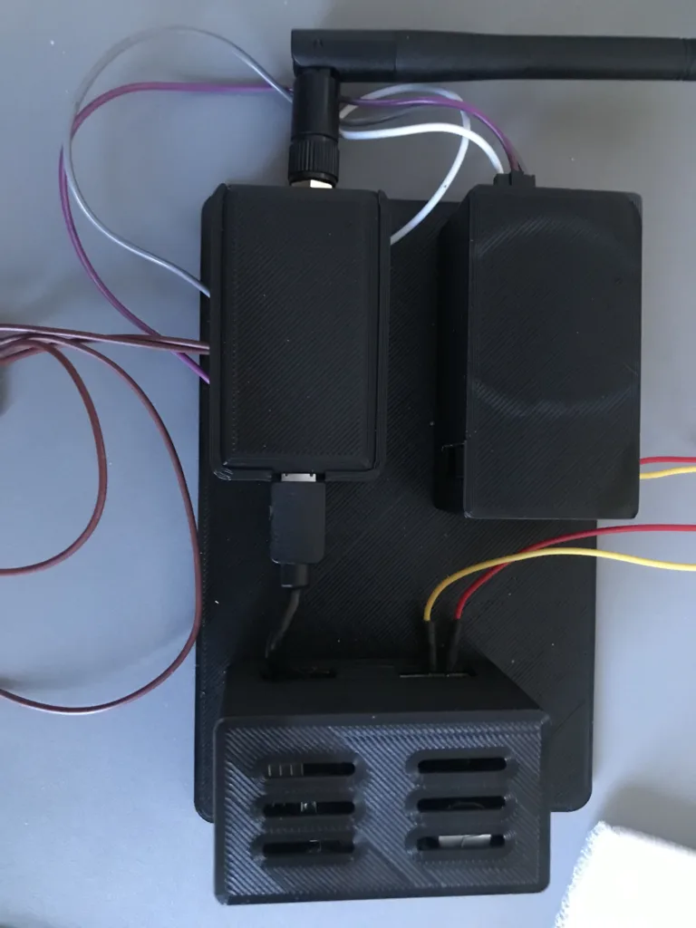
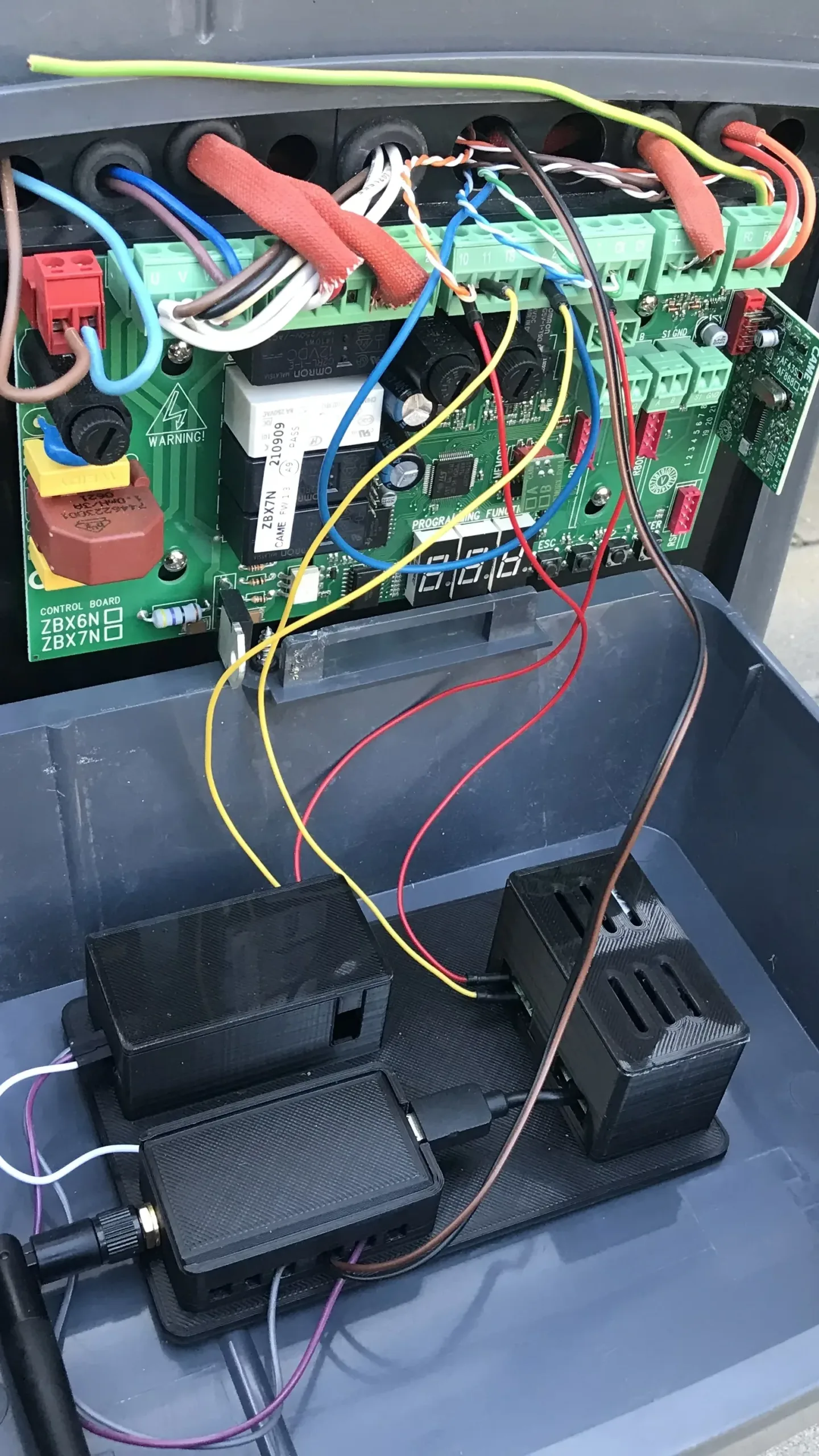
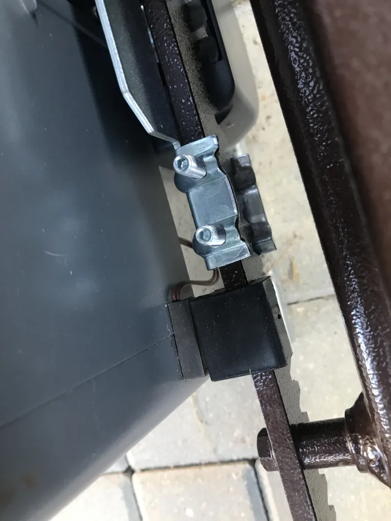
I’ll provide a few pictures of what the actual installation looks like on my end. I modeled a simple little template box to store all the devices securely to avoid any contact as it sits right next to the motor’s main board. With some double-sided adhesive tape on the back secured it to the cover from the inside.
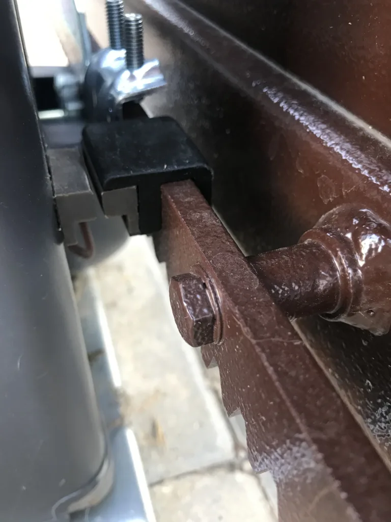
So the point of the actual magnet switch for me was two things. One was to be able to get a status notification on my phone. When I would toggle the gate to open it would send a status message through the Home Assistant app like “Gate Opening” This helps in confirming whether the command was sent as it only sends the notification when the magnets move apart. The same thing goes for closing once the magnets come into contact I get a “Gate closed” message. The mounting point will most likely differ for everyone but I mounted it behind the motor next to where the gate is moving which worked ideally for me. I also 3D printed a simple holder for the magnet to sit on the gate.
So this works as part of an automation I have set up. I’ll add it below just for context as it would still need to be configured from scratch based on your setup. My configuration assumes that a user has a device attached to them (that means their phone) as Home Assistant can onboard your device as an entity when you install the app. In my case, I use an iPhone.
Automation yaml
alias: Gate
description: ""
trigger:
  - platform: event
    event_type: ios.action_fired
    event_data:
      actionName: Gate
    context: {}
  - platform: event
    event_type: mobile_app_notification_action
    event_data:
      action: Gate
condition: []
action:
  - type: toggle
    entity_id: switch.tasmota_gate
    domain: switch
  - choose:
      - conditions:
          - condition: state
            entity_id: binary_sensor.gate
            state: "off"
        sequence:
          - choose:
              - conditions:
                  - condition: template
                    value_template: "{{ trigger.event.data.sourceDeviceID == 'myiphone' }}"
                sequence:
                  - service: notify.mobile_app_myiphone
                    data:
                      message: Gate opening
              - conditions:
                  - condition: template
                    value_template: "{{ trigger.event.data.sourceDeviceID == 'wifesiphone' }}"
                sequence:
                  - service: notify.mobile_app_wifesiphone
                    data:
                      message: Gate opening
              - conditions:
                  - condition: template
                    value_template: >-
                      {{ trigger.event.data.sourceDeviceID not in
                      ['myiphone', 'wifesiphone'] }}
                sequence:
                  - service: notify.notify
                    data:
                      message: Gate opening
          - wait_for_trigger:
              - platform: state
                entity_id: binary_sensor.gate
                from: "off"
                to: "on"
          - delay: "00:00:02"
      - conditions:
          - condition: state
            entity_id: binary_sensor.gate
            state: "on"
        sequence:
          - choose:
              - conditions:
                  - condition: template
                    value_template: "{{ trigger.event.data.sourceDeviceID == 'myiphone' }}"
                sequence:
                  - wait_for_trigger:
                      - platform: state
                        entity_id: binary_sensor.gate
                        from: "on"
                        to: "off"
                  - service: notify.mobile_app_myiphone
                    data:
                      message: Gate closed
              - conditions:
                  - condition: template
                    value_template: "{{ trigger.event.data.sourceDeviceID == 'wifesiphone' }}"
                sequence:
                  - wait_for_trigger:
                      - platform: state
                        entity_id: binary_sensor.gate
                        from: "on"
                        to: "off"
                  - service: notify.mobile_app_wifesiphone
                    data:
                      message: Gate closed
              - conditions:
                  - condition: template
                    value_template: >-
                      {{ trigger.event.data.sourceDeviceID not in
                      ['myiphone', 'wifesiphone'] }}
                sequence:
                  - wait_for_trigger:
                      - platform: state
                        entity_id: binary_sensor.gate
                        from: "on"
                        to: "off"
                  - service: notify.notify
                    data:
                      message: Gate closed
mode: restart
You can go further with this. For example as an idea if you have a camera facing the gate. You could set a timer for the magnet sensor. Let’s say the gate is detected as open for longer than 5 min. Take a screenshot of the camera view and send a notification via the mobile app with a preview screenshot from the camera. In any case, whatever you choose to automate with this is up to you.
Conclusion
To sum up this use case for automating a sliding driveway gate we needed to figure out what the motor accepts as input, and what power it could supply as output and the rest was to get the hardware and configuration in place to achieve the final goal. As mentioned solutions depend on how deep your pocket goes for more fleshed-out and simpler ways of making this work. This is strictly DIY it can also up your costs very much if you are just getting into home automation as the actual parts needed were cheap. But if you need to go out and buy a soldering iron and other tools the initial buy-in is gonna be much higher for some.
This topic has been in draft for a long time and I finally got around to writing it up. If you are reading this during the holiday season. Merry Christmas and hopefully a great 2024.
As always I hope this has helped you out.


Recent Comments