
Flashing the Sonoff RF R3 & Dual R3 with Tasmota
Introduction
I’ve already been running some of my ESP devices with Tasmota and I have a few Sonoff devices that I wanted to do the same and keep control of your smart home locally. Let’s take a look the Sonoff RF R3 and the Dual R3 with using DIY mode and serial flashing. I wrote this in the same practical, step-by-step style I use on my site.
What you’ll need
- USB-to-TTL (3.3 V) adapter (FTDI/CH340/CP2102) with 3.3 V selected
- Female dupont wires, crocodile clips or soldering iron (if needed)
- A computer/laptop with WiFi and preferably a smartphone
- Latest Tasmota build for your chip. I’m using the tasmota bin for the RF R3 and the tasmota32 bin for Dual R3)
Safety first — read this twice
- Always disconnect mains power before opening, probing, or connecting serial to devices that expose live traces. The Dual R3 in particular has GND connected to live AC. DO NOT connect serial while AC is present.
- Use a 3.3 V adapter (not 5 V).
- If you’re not comfortable working with mains, stop and ask for help or use a USB-OTG flash/DIY OTA approach if available.
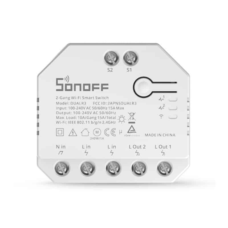
Part 1 — Sonoff RF R3 v1.0: use ITEAD DIY Mode (OTA) or apply jumper wire
Overview
Newer Sonoff R3-style boards support the ITEAD DIY Mode, which allows local LAN OTA uploads and REST control – much easier than soldering the serial pins on hard-to-reach pads. The official ITEAD repository and tools describe the protocol, provide a small tool and note firmware compatibility caveats. Importantly: devices with firmware 3.5.0+ use a different protocol / AP setup and the old DIY tool won’t work the same way.
Try OTA via ITEAD DIY first
To begin with the current method if the device supports firmware version 3.5.0+ then the DIY mode is much simple. Usually it is just enough to press the sync/power button and hold it for about 5 seconds then it will start advertising a WiFi AP “ITEAD-xxxxxxx” and you should be able to reach it throughhttp://10.10.7.1/ and be able to flash it. Which is way easier. But this guide covers the method for older versions.
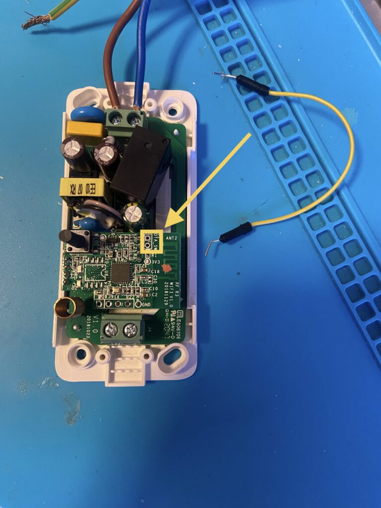
The DIY mode pins are on the inside of the device so just needs the screws to be unscrewed from the bottom and bridging the two pins as shown with a wire/jumper or just solder them together.
Now comes the dangerous part which is we will need to connect the board to AC. So in terms of EU here we are working with 240V mains voltage. Which is dangerous so take necessary safety measures when working with this. I would suggest powering this inside of its enclosure to not shock yourself by accidentally touching it. Once it’s booted the LED should blink twice in intervals that should mean its in DIY mode. What it’s doing now is looking for a specific WiFi SSID name to connect to. What I did in this case is took out my phone and created a personal hotspot with the specified name sonoffDiy and the password must be 20170618sn . Then connect your laptop to this sonoffDiy access point and you can launch the tool_01DIY85(v3.3.0).exe which you downloaded from the itead repository. If everything was correct and the devices connected successfully they should be detected by the tool.
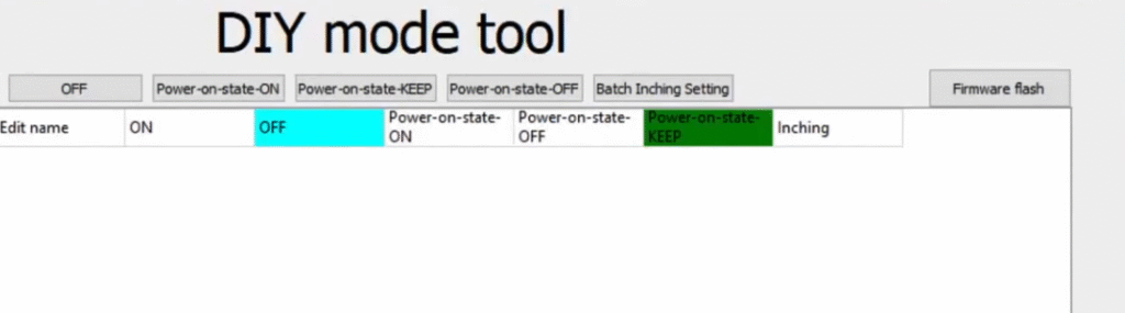
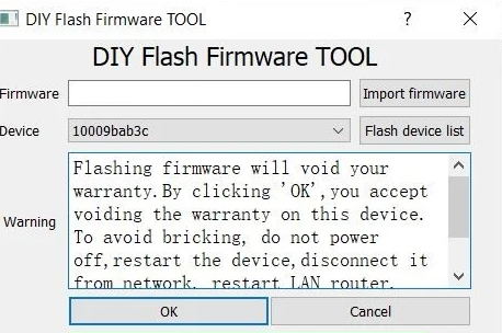
Next you can select Firmware flash in the corner and in the new window you can now provide the Tasmota firmware .bin file for flashing. The RF R3 device should support the regular Tasmota version as of last checking v15 does work. You can easily get it from the ota site here . Or just check their GitHub repository. Now provide the .bin file and flash it.
Once flashing is done the device will restart and you should see a new WiFi access point show up like “Sonoff-xxxx”. You will the preferably using your computer connect to it and in your browser attempt to go to 192.168.4.1. That’s usually what I’ve seen the IP address is when the device creates it’s own app. But if you can’t find it you could use a simple app like Angry IPScanner or similar to just quickly ping the subnet to find any active devices and identify the IP’s. Once connected from here you are greeted with the Tasmota UI interface. First thing I would suggest doing is to connect it to your local WiFi network so that you can easily access it from now on. Take a look at the Tasmota wiki for the menu options. Overall the only meaningful change here is to probably go to Configuration -> Module. And select the Module type as Sonoff RF and save it so that it uses the correct type if it’s not already set.
That’s it you have the device running Tasmota firmware and you can configure MQTT and anything else you like. In regards to the RF functionality it remains separate from the Tasmota firmware meaning you don’t really have control of what happens during a remote button press. So the functionality still works and remains the same as if it was on original firmware. The pairing of the remote is still by pressing and holding the power/sync button for 2-3 seconds until a red light start flashing and then you can pair a compatible Sonoff remote by pressing the remote button. You should hear the relay click which means it got paired.
As a side note there is an article that describes how to get the RF module working as a 433MHz gateway. I have not tested it since I already have a RF Bridge running Tasmota so it’s not exactly needed. But if you are interested check it out here.
Part 2 — Sonoff Dual R3 Serial Flashing
Overview
So this one is safer to use. But just in case you had it powered on before attempting this do note that the capacitors inside may still be charged so let the device sit for a while to discharge them. While the device doesn’t have a DIY mode. Or at the very least I am not aware of it. For this I am using the FT232 adapter with some dupont cables and crocodile clips. As I just want to avoid soldering, but it would probably be easier.
The process
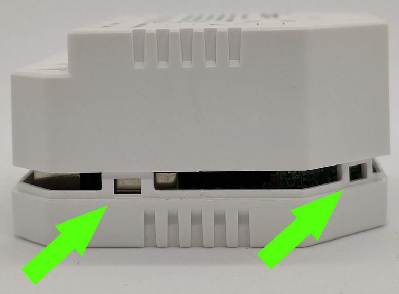
First we need to open the device up. It has no screws that hold it in place but rather clips on the sides. I used a flat head screw driver to pry the sides to expose the clips and just nudge/bend them inward to release and pull off the casing. Careful here to not let the tool you are using to slip as to not puncture or dislodge anything on the board.
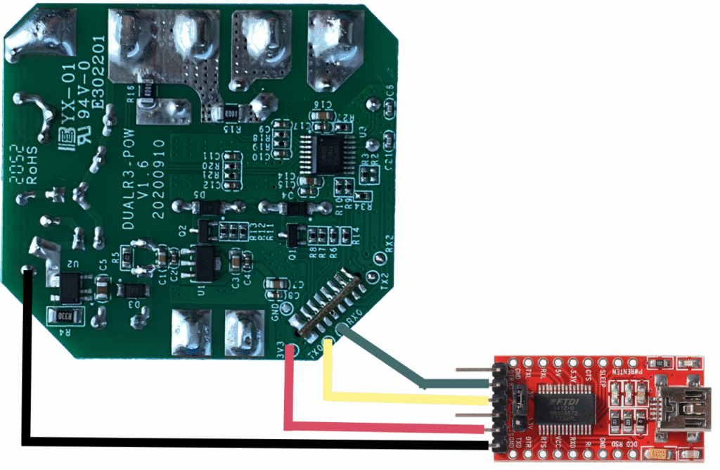
Once you have it out you can identify the 3V3, TX, RX and GND pin’s on the board. There is a GND pin next to the 3V3 but not as easily accessible. Instead just use the one on the other corner. Here is a simple wiring setup with the serial adapter.
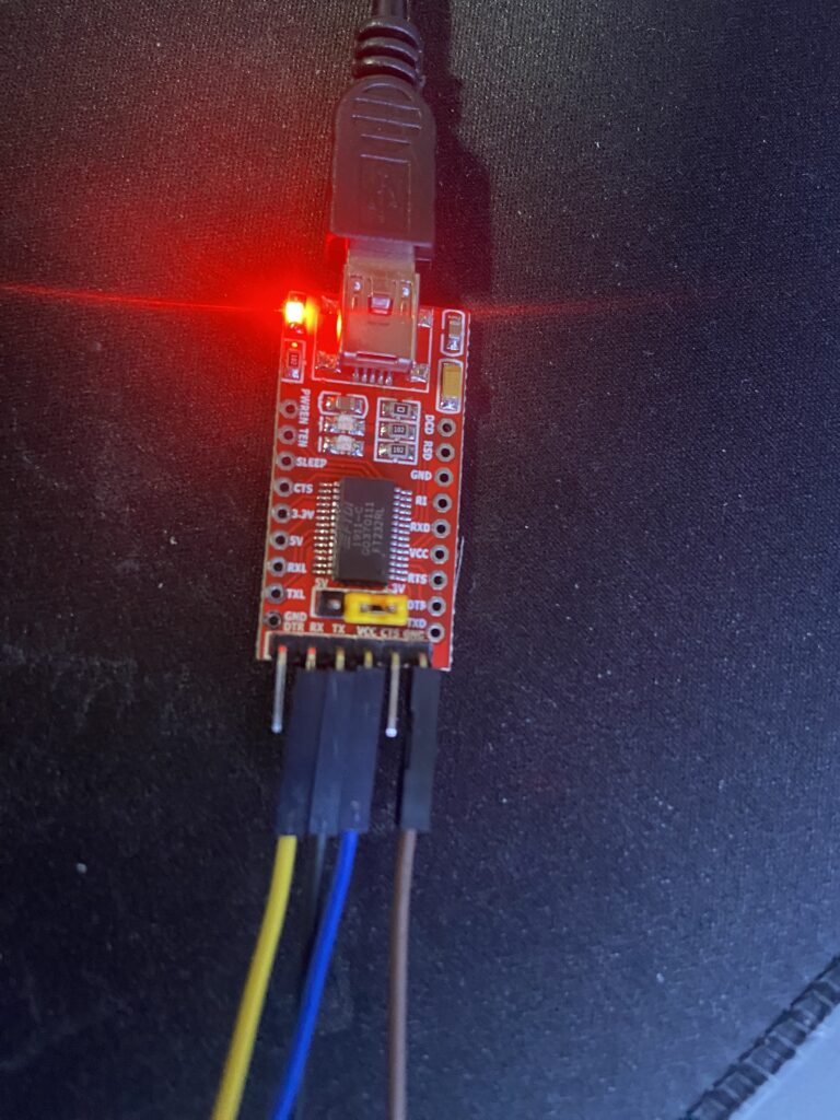
Then we connect the serial adapter via USB to our computer. The serial adapter should light up.
This should come up as a COM port. You could check and identify which port it was assigned in Device Manager in Windows. Next to flash it I like to use the Web Installer.
Now you can select one of the available Sonoff firmware files to flash. In this case we are flashing the Tasmota32 bin. Or you can flash the Tasmota32-Bluetooth version as well as it’s also supported to use as a gateway if you prefer that.
If the flashing was successful. We can the unplug and disconnect all the wires. Put the device back in it’s housing and we will need to plug it into regular mains power to start it up. Once it’s up and running you should again similarly see that it has a WiFi access point up which you should connect into and configure it through the Tasmota UI same as with the device in Part 1. This device as much as I know may still not have a device module template so you can still use the one below. To apply it in the Tasmota UI navigate to Configuration -> Other. And in the Template field you can enter it , toggle the Activate button and Save it.
{"NAME":"Sonoff Dual R3","GPIO":[32,0,0,0,0,0,0,0,0,576,225,0,0,0,0,0,0,0,0,0,0,7296,7328,224,0,0,0,0,160,161,0,0,0,0,0,0],"FLAG":0,"BASE":1}Conclusion
And that’s it. While these devices are older models and are more involved in terms of getting them working with firmware like Tasmota. It’s worth if you want the local functionality and full control with a lot of integration since it can support MQTT, have it’s own integrate rules to act up one are be automated through home assistant. Newer devices as I have seen now usually have the easier way to reach DIY mode for flashing. But in any case I urge you to check the resources below to identify which devices are better suited for you if you want to go this route with Tasmota.
Troubleshooting
If you have issues with getting a connection with your PC via the Serial adapter make sure the adapter is recognized and that your computer has the drivers for it.
If flashing fails due to the file size as some of the Sonoff devices have limited flash memory. You can always flash the tasmota-minimal.bin first. This will give the basic functionality and you can then try flashing other versions. In some cases it may be worth trying to flash a compressed bin.gz images as it I have had more success with them in the past.
If you have browser issues with the Web Installer. You can always use a program like Tasmotizer instead, which should work ideally.
Helpful links
Tasmota device repository
Tasmota documentation
General flashing guidance for starters
Tasmota GitHub repository
FTDI Drivers
Tasmotizer


Recent Comments