
Turning an HP EliteDesk 800 G2 Mini into a router
Introduction
I have an HP EliteDesk 800 G2 Mini (65W) which in general is a solid little office PC that HP sold by the millions, and now they show up on the used market for pocket change. The plan was to turn one into a proper router, and honestly it’s not that hard, it just needs a second NIC and that’s where the fun begins. The machine already has a gigabit port onboard and an M.2 A+E slot that usually holds the Wi-Fi card, so with a cheap adapter card you end up with two NICs in a box the size of a sandwich. Add Proxmox on top and run OpenWrt as a VM, and you get a router that costs less than a mid-range consumer one and does a whole lot more. I’ll go through the disassembly in detail since that’s the part where people get stuck, and then the first steps to get it running. Every network is different so I won’t go into full configuration here, just enough to get it passing traffic.
What you’ll need
Before we start, the inspiration for this build came from Jonathan Gazely’s excellent guide on adding multi-gigabit support to the G2 Mini, linked at the bottom. He used a 2.5G card with an RTL8125 chip and cut his case with a hacksaw to make it fit. I went a different route, a cheaper 1G card with an RTL8111H chip and 3D printed mounts instead of cutting metal. For a router gigabit is honestly enough for now, and the printed parts keep the whole thing reversible. Which is nice.
| Part | Qty | Notes / recommended spec | Example / link |
|---|---|---|---|
| HP EliteDesk 800 G2 Mini (65W) | 1 | Any G2 Mini works, 65W version is the common one | Used market |
| M.2 A+E to Gigabit Ethernet card (RTL8111H) | 1 | 10/100/1000Mbps, single RJ45, cable with two push-on connectors at 90° | Aliexpress link |
| 3D printed SSD mount | 1 | Repositions the 2.5″ SSD so the drive cage clears the NIC card, print in PETG | STL from my files |
| 3D printed RJ45 mount | 1 | Fits the rear opening left by the DisplayPort daughterboard, holds the port from outside | STL from my files |
| Small Phillips screwdriver | 1 | Most of the screws inside are Phillips | – |
| M3x10 Screws 6x | 1 | For mounting the SSD and NIC | Maker Supply |
| Flat blade screwdriver / knife | 1 | For lifting antenna connectors and the daughterboard | – |
| Torx bit | 1 | For the heatsink screws, a flat head also works | – |
| Thermal paste + alcohol wipes | 1 set | Heatsink has to come off, fresh paste needed | Any brand |
| USB stick | 1 | For the Proxmox installer | 8GB+ |
Step 1: Take it apart
The G2 Mini is annoyingly well built for something this small, so there’s a proper order to the teardown. Follow it and you won’t break anything. The service manual covers this too, but here’s the short version.
Start with the lid. There’s a small latch at the back with a screw, unscrew it and slide it and lift the lid off. Inside you’ll see the 2.5″ SSD bay on the left. Gently pull the SATA connector off the drive, then slide the SSD out of its cage. There’s a metal latch you pull sideways, then the drive slides towards the rear and lifts out.
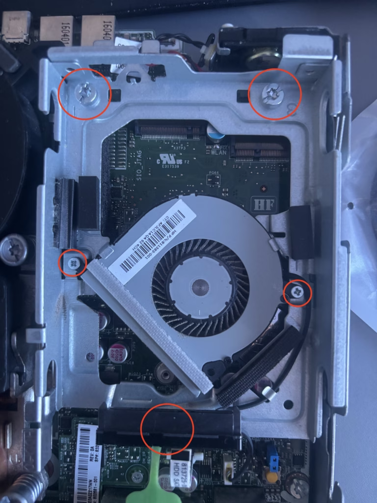
Next the drive cage. Undo the three bolts holding it in place. Careful here, the case open sensor (the little switch that tells the board the lid is on) slides out of the front of the cage, don’t lose it and remember where it goes. Put the cage aside for now. The fan has a connector cable that you will need to unplug its next to the SATA cable. Keep the screws as we will reuse some of them
Step 2: Out with the Wi-Fi card
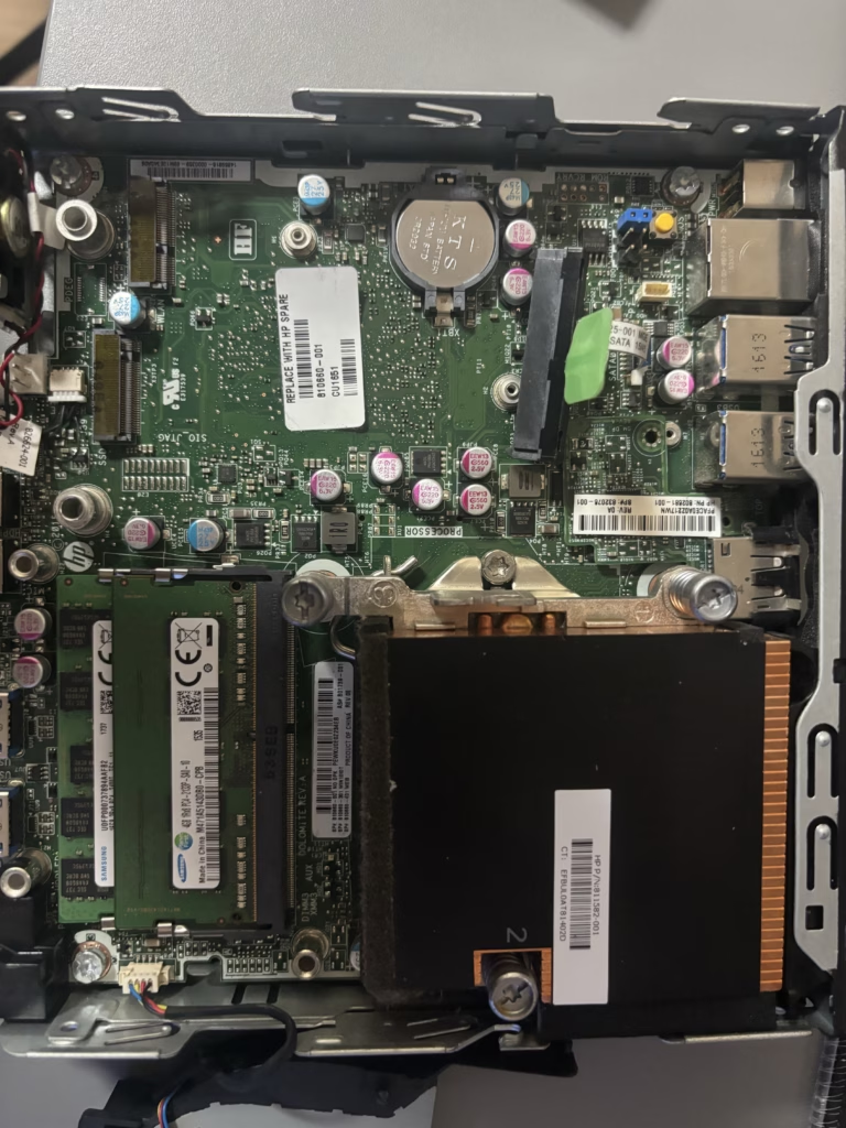
The M.2 A+E slot we’re going to use is the one that normally holds the Wi-Fi/Bluetooth card. If yours has one fitted, remove the two antenna cables first, lift the gold connectors off the board with a flat blade or knife, gently (best would be a plastic tool or just your finger nails) It should come off easily. Then undo the retaining screw and pull the card out. Tuck the antenna wires down the side of the motherboard so they’re out of the way. In my case I didn’t have the Wi-Fi board so the slot was already empty.
Step 3: Fan and heatsink out
Now the system fan. Lift the black plastic tab to rotate the fan unit upwards, then slide it towards the front of the machine to free it. Don’t yank the cable. Set it aside or unplug it to not break it.
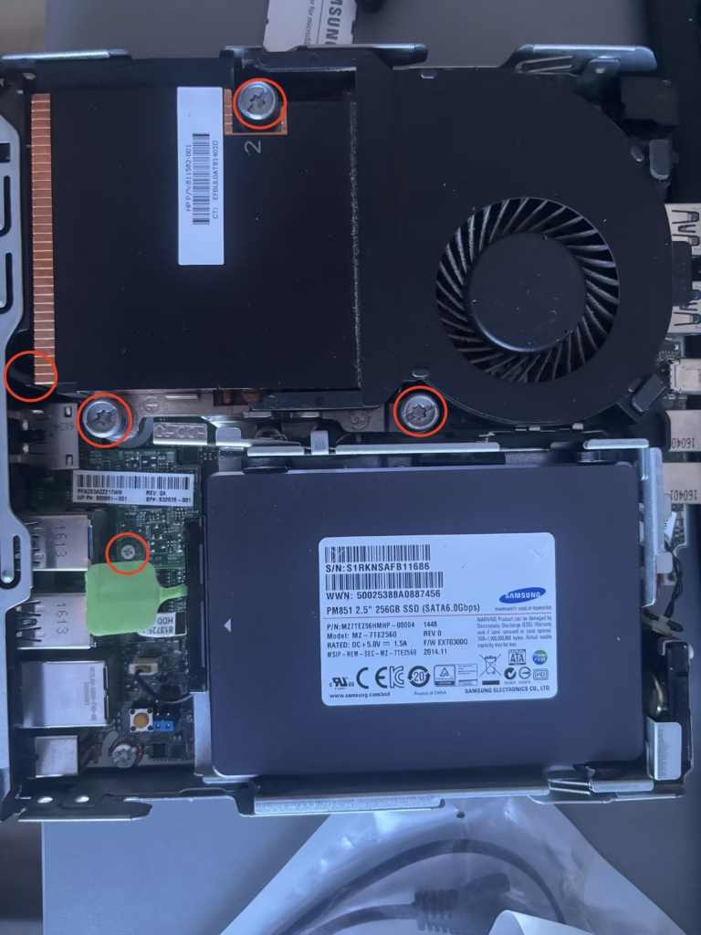
Under the fan is the CPU heatsink, held by three screws. They’re Torx but a flat head works fine. Undo them, flip the heatsink over and put it somewhere clean, try not to get thermal paste on anything. Clean the CPU and heatsink with alcohol wipes, we’re going to need fresh paste later anyway. The two marked screws at the edge ar for the daughterboard, while they can be unscrewed , you wont be able to get the board out until the heatsink is off.
Step 4: The DisplayPort daughterboard comes out
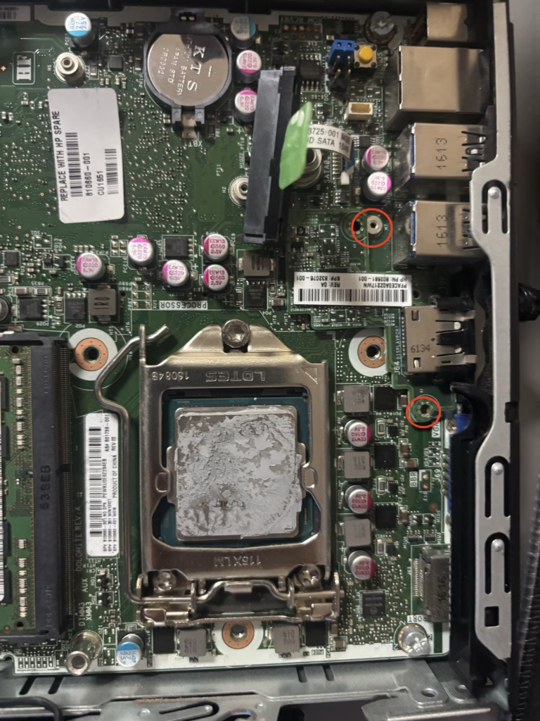
With the heatsink out of the way you can finally see the two small screws holding the daughterboard in place. That’s the module on the back of the case that gives the G2 Mini its extra DisplayPort. Undo both screws and lift the daughterboard up from the motherboard. Sometimes it sticks to the foam around the opening in the case, so give it a gentle wiggle. This is the piece we’re replacing, out goes the DisplayPort and in comes our RJ45. The connector is underneath the board so just lifting it upwards will unplug it. Keep the screws from the daughterboard, since if you didn’t have a Wi-Fi board we can use the screws for securing the NIC board later.
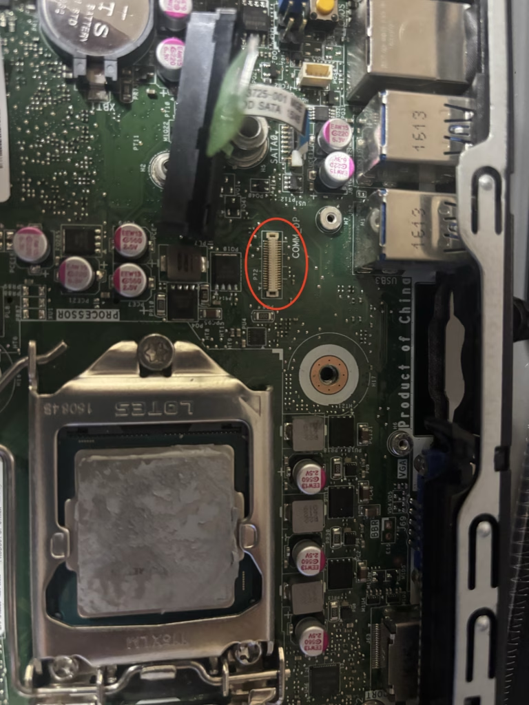
Step 5: In with the NIC card
Now the good part. The card I used is a generic M.2 A+E to Gigabit Ethernet adapter, single RJ45 port, RTL8111H chip, 10/100/1000Mbps. It’s the same form factor as the Wi-Fi card that just came out, so it slots straight into the same M.2 A+E slot. Line up the two notches, push it in at a slight angle, and hold it down with the same retaining screw the Wi-Fi card used.
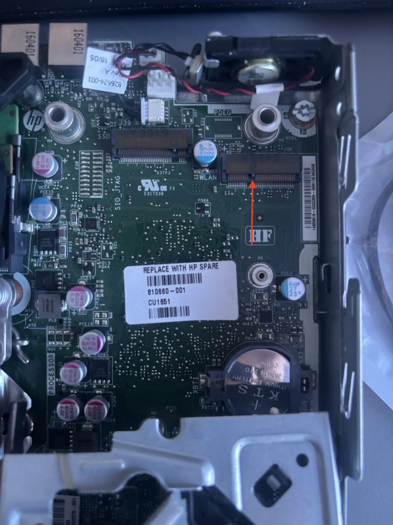
One thing to watch, the card has a cable coming off it with two push-on connectors at the end, they carry the Ethernet signals to the port. When you fit the card make sure the cable routes towards the rear of the case, it needs to reach the RJ45 mount. And don’t overtighten the screw, these little cards bend easily. Screw has a designated hole for the mounting as marked behind the cable.
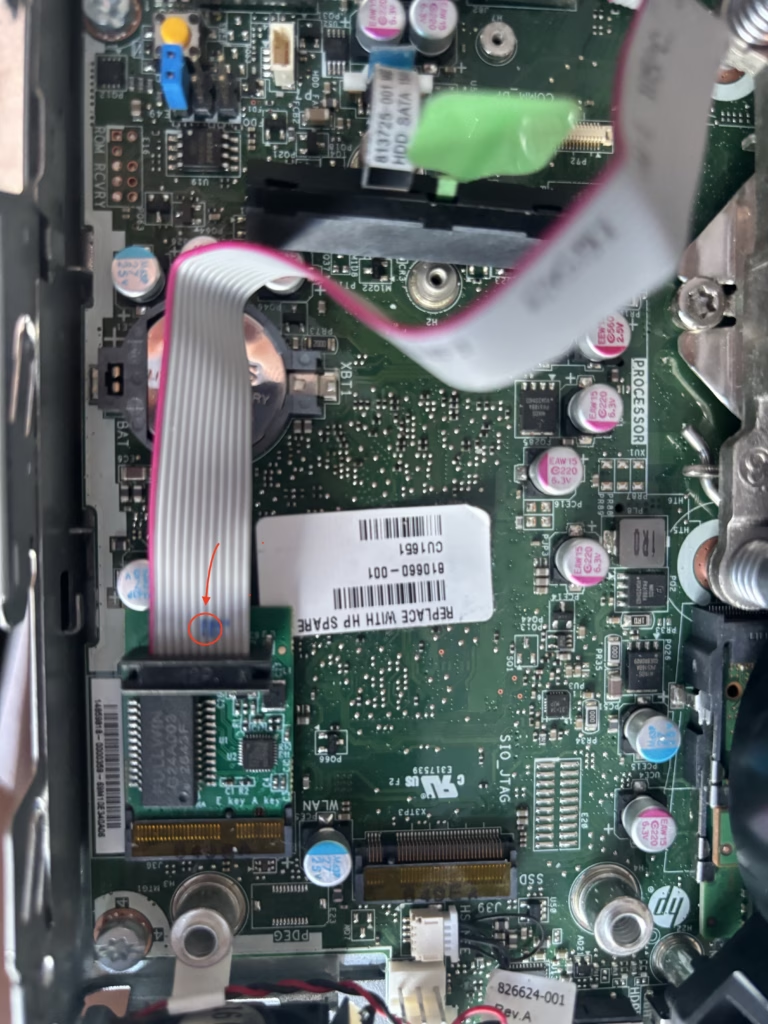
Step 6: The 3D printed parts
Here’s where this build differs from Jonathan’s. He cut his case and drive cage with a hacksaw to make everything fit. I’d rather not butcher a perfectly good mini PC, so I printed two parts instead. So this is totally reversible if needed.
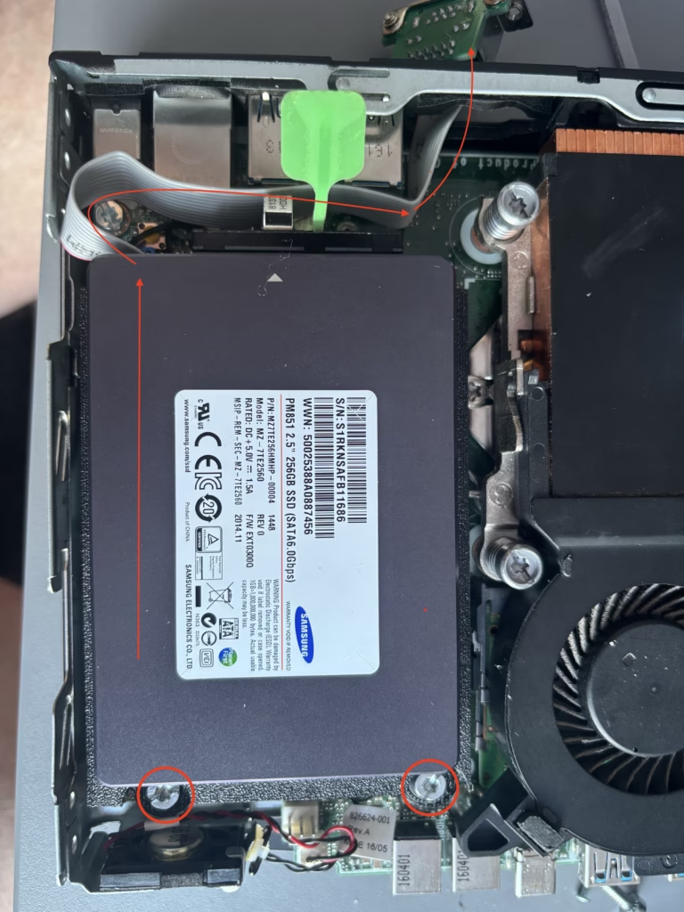
First the SSD mount. The problem, with the NIC card and its cable in place the standard drive cage placement gets tight, and in some layouts the drive cage actually fouls the card’s connectors. The printed mount repositions the 2.5″ SSD slightly so everything coexists happily. The SSD sits in its own little tray, mounted on the same standoffs the cage used. No cutting, no filing, no metal shavings in the machine. The fan that sits underneath the drive has a slightly shifted place to screw on since it hits the connectoer of our NIC board and doesnt fit. The 3D printed SSD mount fixes that.
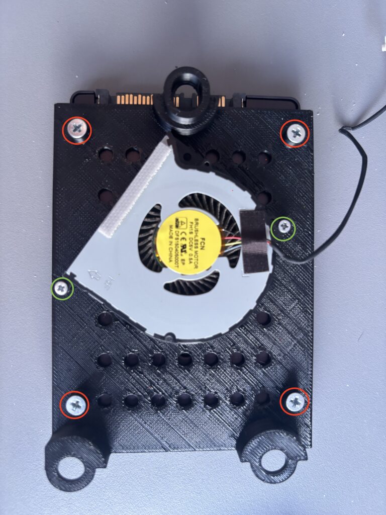
The additional screw in our list we needed will go here 4 of them for the SSD to secure it. And we will reuse the two screws from the fan to put it in place. As can be seen the front of the SSD where the connector goes blocks the screw mount hole. In this case a workaround is that it will just slot around the mount and we will just use the two screws from the HDD caddy. It’s secure enough to hold it in place. It’s really not going anywhere at this point. This is how I have it mounted and the cable routed around to the end of the mini pc.
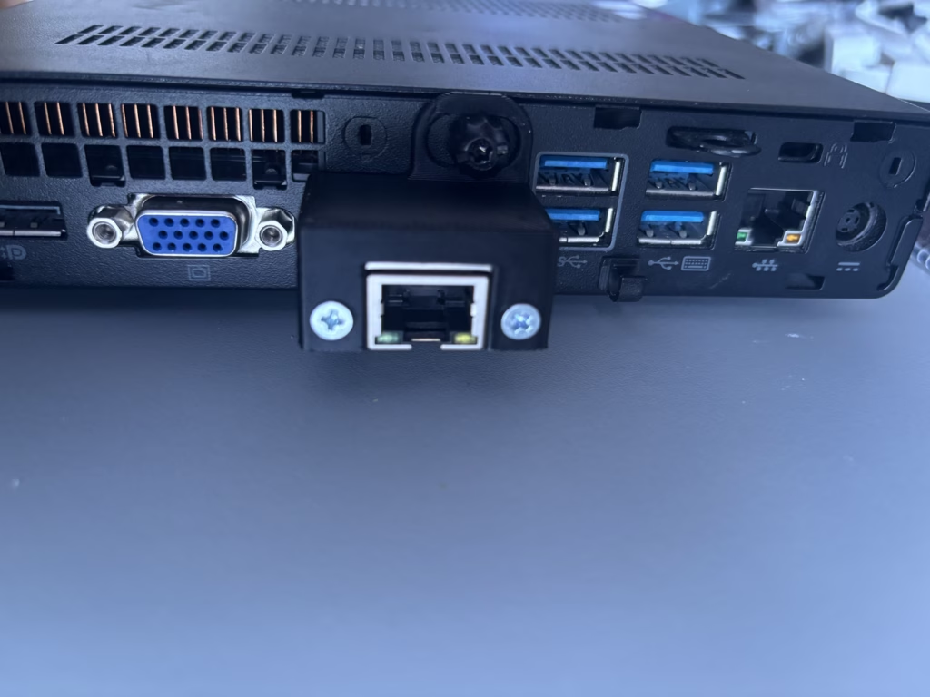
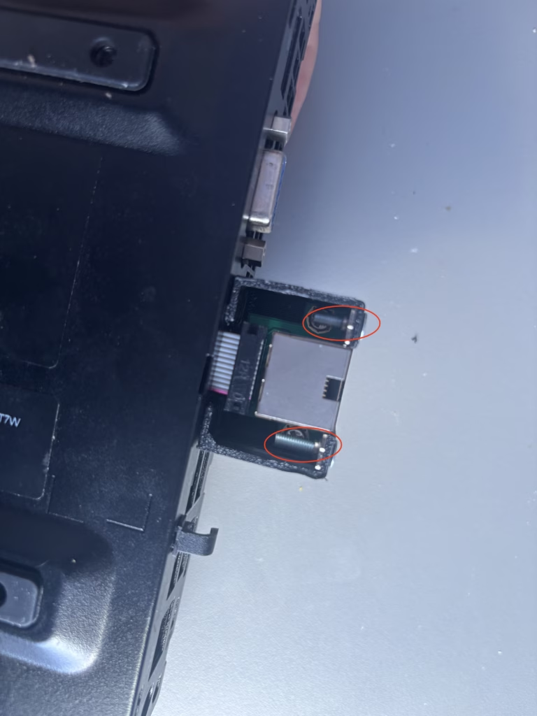
Second the RJ45 mount. This is the satisfying one. We will need to unscrew the black locking screw out that holds the panel cover of the whole mini pc. The rear opening left by the DisplayPort daughterboard has enough space to route the cable for an RJ45 port, so the printed mount clicks into that opening from the outside and holds the Ethernet connector in place. The NIC cable’s two push-on connectors plug into the back of the port, the mount screws down with a couple of small bolts, add the panel securing screw back in through the hole, and that’s it. A clean, gigabit port on the back of the machine where the DisplayPort used to be.
Step 7: Put it back together
Reassembly is the reverse of the teardown, with a bit of care. Route the NIC cable around the edge of the case, away from the CPU area. You do not want it pinched between the heatsink and the board, and definitely not under the drive cage. Apply fresh thermal paste to the CPU, refit the heatsink and tighten the three screws evenly. The fan just rests back into its grooves. Refit the drive cage with the printed SSD mount inside, slide the case sensor back into place, plug the SATA cable back in and put the lid on.
Boot it once to check everything works, you should see the new NIC in the BIOS or, once the OS is up, in dmesg. If the port doesn’t come up check the cable connectors first, they’re the fiddly bit. To clarify this as worked and identified automatically for me in BIOS version 2.61 I updated the BIOS via network as described in the multiple ways here: https://support.hp.com/us-en/document/ish_4123786-2338478-16 . Other BIOS most likely will work. I am just providing what has worked for me in this case.
Step 8: Proxmox (the easy part)
For the software side I went with Proxmox. It’s free, it’s a proper hypervisor, and it means the router runs as a VM that I can snapshot before touching anything. Every network is different, so I’m not going to give you a full configuration here, just the first steps to get it running.
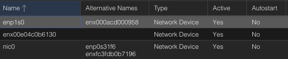
Grab the Proxmox VE ISO, flash it to a USB stick, boot the mini PC from it and follow the installer. It’s mostly just picking a disk and a password. When it reboots you get a web UI at https://IP:8006. Log in and you’re looking at the datacenter view. Go to the node, then Network, and you’ll see the machine’s NICs.
Step 9: The OpenWrt VM and attaching the NICs
OpenWrt runs as a VM in Proxmox. Download the OpenWrt x86_64 generic image, upload it to the Proxmox storage, and create a VM that boots from it. The important bit is attaching the NICs properly, this is where people get stuck. In the VM’s hardware tab add two network devices, one on a bridge for the LAN side and one for the WAN side. My setup, the built-in NIC handles LAN and the M.2 card handles WAN. Make sure each bridge in Proxmox is bound to the right physical NIC, otherwise OpenWrt will see two ports that lead nowhere useful.
Boot the VM. OpenWrt’s first boot gives you a LAN address out of the box, so open its web UI in a browser, go through the basic setup wizard and assign the interfaces, one as WAN and one as LAN. That’s honestly the whole trick, get the right NIC on the right side and everything else, firewall, DHCP, DNS, VLANs, is just your network’s business. Start with a basic config, get it passing traffic, then build up from there. And thanks to Proxmox you can snapshot the VM before every change. Which is very nice to have.
Safety, testing & troubleshooting
- Unplug the mini PC and ground yourself before working inside it.
- NIC not detected in the OS → reseat the card in the M.2 slot and make sure the retaining screw is in, they can work loose.
- Ethernet port has no link → check the two push-on connectors on the card cable, they’re the fiddly bit and easy to knock off during reassembly.
- OpenWrt only sees one interface → check the VM hardware tab has both network devices attached, one per bridge.
- Traffic flows but no internet → most likely the WAN bridge is bound to the wrong physical NIC, double check which port is which in Proxmox Network settings.
- Fan noisy or temps high after rebuild → heatsink not seated properly, redo the three screws evenly and reapply paste.
Conclusion
Is it worth it? For me, absolutely. The 800 G2 Mini cost less than a mid-range consumer router, uses about as much power at idle, and now runs a real firewall OS with proper logging, VPN, VLANs and full control, plus I can run other VMs on it if I ever need to. I would probably recommend getting the 2.5GB NIC card since it can support higher speeds. The whole build is reversible too, thanks to the printed mounts instead of the hacksaw. The only real downside is that it’s one box instead of a neat little router appliance, but honestly, for what you get, I’ll take it.
If you do this yourself, take your time with the disassembly, don’t lose the case sensor if it’s present, and triple check the NIC cable before you tighten the heatsink. As always I hope this has helped you out.


Recent Comments