
Wi-Fi on your Lay-Z-Spa. Great way to remote control
[Updated 2025-08]
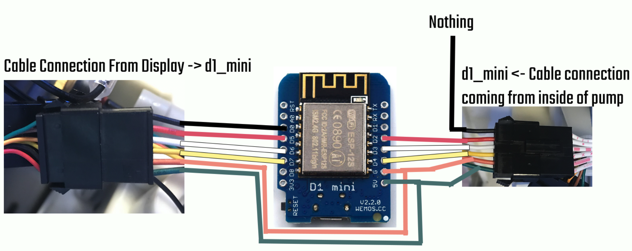
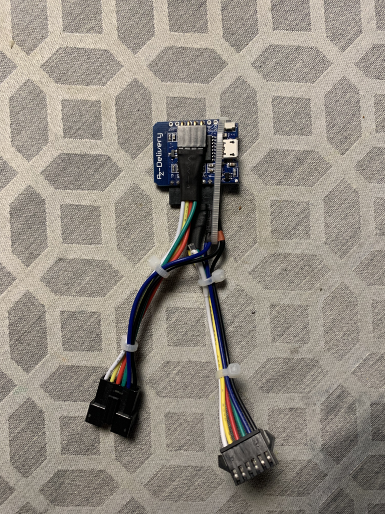
Due to some discussion in the comments I decided it might be time to pull out the pump since it was still in storage and do an update to the latest version. The version we are updating to as of writing is v4.4.8. I’m currently going from v4.1.3 to the latest one. So as I have checked everything remains the same. The only changes needed to be done in the code is to set the board under the [env:nodemcuv2] to board = d1_mini. All the other steps remain the same we build and upload to the board and not to forget also upload the Filesystem Image. The board will start flashing on reboot because the pin out has reset in the config so login via the hotspot Access Point that it creates and do the necessary changes under the Hardware Config page. For me the WiFi and MQTT settings were reset so I needed to reconfigure it. Everything else remains the same. The UI has been visually updated and some optional features have been added. I’m also adding an updated image of the wiring which hopefully gives a better understanding of what wires go where between the Display -> d1_mini <- Pump.
[Updated 2025-06]
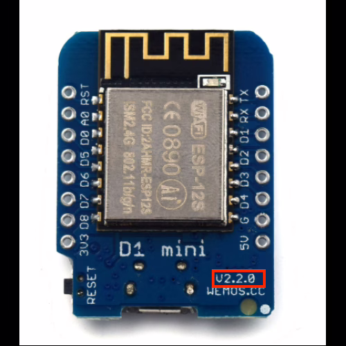
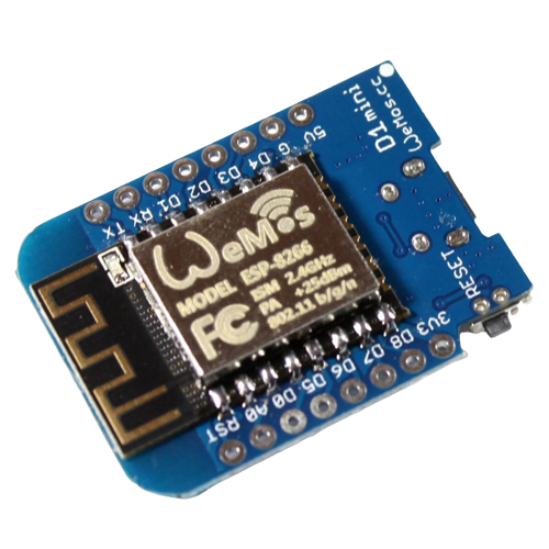
A noteworthy update that was shared in the comments. If you go along with the guide and attempt to use the WeMos D1 mini board. Make sure to get the v1 or v2 (v2 is used for this guide which will be the recommended version) board version with the micro USB port. As pointed out by Gerwin in the comments, v3 and most likely newer versions will not function properly. The board usually has the version outlined on the board itself to be able to confirm.
[Updated 2024-08]
A small update that may be worth noting. Nothing has changed as of the last update. Some new versions of these integrations were released (ver. 4.4.5 at the time of writing) but did not impact the guide I previously wrote. So this guide can still be followed to achieve the results stated. Regarding some news, there are now users selling complete kits that add the Wi-Fi functionality so if you are not tech-savvy enough to attempt this you may be interested in just getting a pre-made one:
https://github.com/visualapproach/WiFi-remote-for-Bestway-Lay-Z-SPA/discussions/615
Disclaimer: I am in no way associated/affiliated with the post above, nor have I purchased this item or confirmed its legitimacy. I am solely basing this off of the reviews and comments left on the post that the seller appears to be legitimate in what he offers. Take this with a grain of salt and if interested, buy at your own discretion.
[Updated 2023-06]
Since last summer the Lay-Z-Spa has been in storage. In the meantime, I have gotten an explosive amount of questions regarding this year’s update as it seems many are trying to find a solution on how to Wi-Fi enable their hot tubs. So here is an update.
As of writing the current version of the integration is v4.1.3 which we will be using.
The parts/tools that are mentioned in the original guide still hold up to this day so you can still use the same ones if you are doing this fresh or upgrading an existing install. The guide assumes you have the same model pump S100101 and the d1_mini board with 5V pin out and Wi-Fi functionality.
The setup and upgrade
We download the latest version of the code from visualapproach repository. Extract it somewhere that we are going to work with it. Nothing changes here from the original guide we will still use Visual Studio Code to perform all the actions. We use PlatformIO to open the code folder. But this time the only change we need to make is the board to d1_mini.
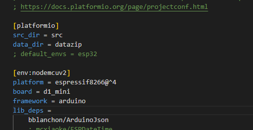
Set the parameter as in the screenshot:
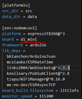
board = d1_mini
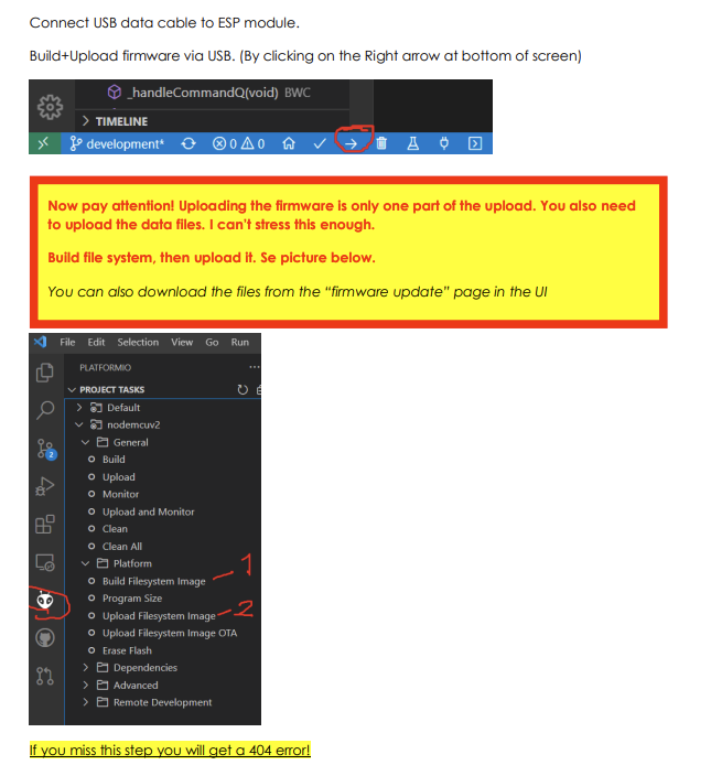
That’s all the changes we are going to make in VS Code. We now connect the board if we haven’t already with a USB cable and compile and upload the code. Follow the picture below for the proper upload steps to avoid errors.
Do keep in mind that if you are using my old guide as a setup for your board or you are upgrading. The pin out and your Wi-Fi/MQTT settings are reset to default and you will need to set up this again.
After the upload is complete your board should be accessible once again via http://layzspa.local I urge you to set up the basic settings like Wi-Fi so you have connectivity after you unplug it and use it as normal.
Once the UI is opened in your browser you will notice if you used it before it is slightly different. The first thing to do is click on the hamburger menu button in the top-right to open the menu. We should first go to Hardware Config and adjust the settings to our board and pump.
So here we have a multitude of settings that were not available before. This is why we no longer need to set the pump model and pinout in VS Code because it is now all done through the UI. Pretty neat!
The settings for the pump model number S100101 are as below in the screenshot. You will also need to set the PCB settings and Pinout if you soldered the wires the same way as in the original guide.
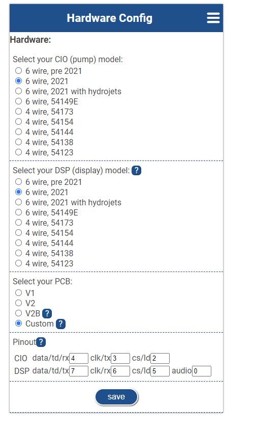
So we set it to 6 wire, 2021. PCB is set to Custom and Pin out is CIO: 4/3/2 and DSP 7/6/5/0. If your board or pump or soldered pins differ you must adjust this accordingly to your model/board.
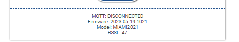
We save the config and restart the board from the hamburger menu. If everything was correct you should see your model changed at the bottom of the main menu based on your settings.
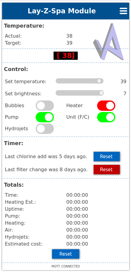
You can test if it works properly by adjusting the settings. The way I like to test that it works is to enable the Bubbles function which will make the pump blow air. As well as adjusting the temperature settings. I would not advise trying the filter or heater options since I do this unplugged and it has no water inside so we don’t want to damage any internals.
So that is pretty much it. It has become much more straightforward to do with fewer parameter changes in VS Code. You can still follow the old method regarding the programs/tools you need. Just use this refresher for the rest once you have everything built and ready.
As always I hope this has helped you out. Happy bathing! Be sure to check out my other posts like:
Using 3D printing to improve your Lay-Z-Spa experience
If you are interested in integrating your hot tub in Home assistant you can check out this post here:
Home Assistant Hot Tub Integration
[The old method from 2022]
Since the start of summer, I have noticed a sale for some of these Lay-Z-Spa inflatable hot tubs. So I decided to get one. We used it for a few weeks outdoors in our yard and I noticed something. We usually tend to go in at the end of the day and that usually means not forgetting to heat it so that it is at the right temperature we want it to be. Sometimes you turn it on and leave the filtering on and forget the heating. Once the evening comes you go out and see that you forgot to heat it up. Bummer.
Since then I have decided there has to be a solution to this. Of course, Bestway offers pumps with Wi-Fi-enabled pumps and an app to accompany them. But most hot tubs do not include this feature and the pumps alone cost almost the same as the whole hot tub. Here comes a DIY solution courtesy visualapproach on GitHub.
You can find the page here:
https://github.com/visualapproach/WiFi-remote-for-Bestway-Lay-Z-SPA
The solution
The idea of this is we add a module inside the pump that interfaces with the pump itself and the display. Also provides Wi-Fi connectivity with a Web interface and remote controls. This supports many different hot tub models from Bestway. The personal one that I am using is the Cancun which has the 2021 pump on it, not like the older egg-shaped models. The features of it are the same as the Miami version except for the texture of the liner.
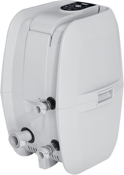
First off for this method to work we need to identify the pump model. There is a sticker on the side of the pump that will tell you what model you have. For this specific setup, I can confirm it works with model number S100101.
If you have the same one you can completely follow along to get this to work. If it is different or you have the egg-shaped pump better to refer to the GitHub page as there is better documentation on different models and what parts you need to make this work.
For this setup, we will be using a WeMos D1 Mini board.
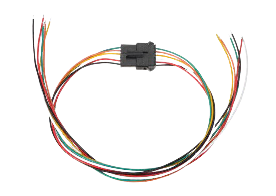
A pair of male-to-female JST-SM 6-pin connectors
Soldering iron, a screwdriver, and a micro USB cable for connecting it to our PC.
Firstly you need to disassemble the pump and open it up to expose the wiring. You should disconnect the pump from the tub and power it off. There are 6 screws that we need to remove around the middle of the pump they can be accessed from underneath in the groves.
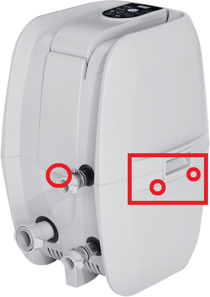
Check the locations underneath on each side, front, and back. You will find holes and you need to remove the screws to be able to lift the top half off to expose the connections. Take care when lifting the top half the handles for lifting on the side might come off. That is normal don’t worry you can put them back in later. You will also want to take care to not lift it too much off as the wire that connects to the display is not that long and you don’t want to damage it because we will need to use it. For easier use going forward, you can disconnect the cable.
We now have the pump prepared for modding. We will need to prepare the WeMos board with the code that is needed to control it.
Download Visual Studio Code and install it. https://code.visualstudio.com/
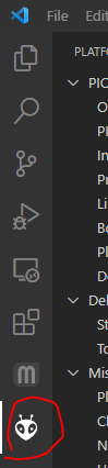
Within the application go to Extensions or Ctrl+Shift+X search for PlatformIO IDE and install it. It might ask you to restart or reload the application too. You will see the new icon available here
Download the latest release from the GitHub page https://github.com/visualapproach/WiFi-remote-for-Bestway-Lay-Z-SPA/releases
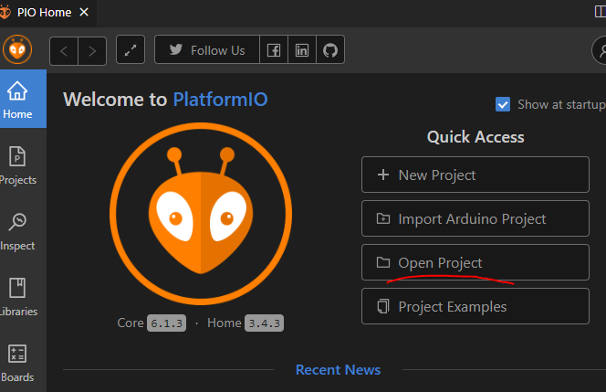
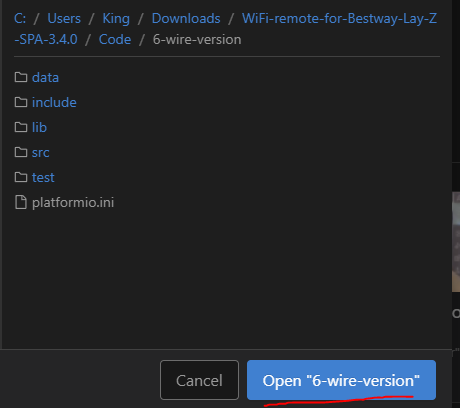
Extract the contents to your preferred location. Via the PlatformIO home page open your project and navigate to the extracted folder with the 6-wire version
Once inside the folder click to open it
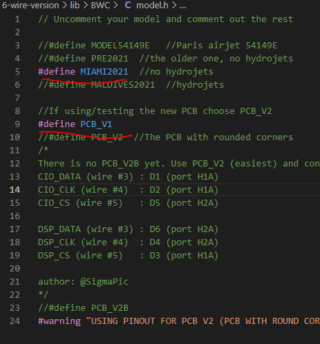
You will have an editor with a list of files on the left side. First, let’s open model.h, uncomment the Miami model, and comment out the PRE2021 with the // symbols. I also use the PCB_V1 version but I do believe the V2 can be used. So comment accordingly
At the bottom, you should find the platformio.ini file. Let’s open that up and define our board as the WeMos D1 mini
Next, we will open the BCW_6w_type1.h file and define the pins that we are going to use on our WeMos board.

Those are the pins we will solder the JST connector wires to. Before we start soldering let’s build and upload our code to see if it works correctly.
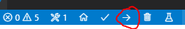
Upload the sketch via USB with the arrow at the bottom left corner
Once that is done we need to also do it via PlatformIO as it will give you a 404 error when trying to connect if you don’t do this. Click the PlatformIO icon and go to Project Tasks>nodemcuv2>Platform. Then Build Filesystem Image.
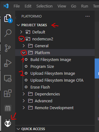
Wait for it to complete and then Upload Filesystem Image. Once both are done the WeMos will start providing a Wi-Fi hotspot called Lay-Z-Spa Module. The password for it is layzspam0dule. Once connected you can access the module via your browser by visiting http://layzspa.local. Click the three lines at the top and go into Network Config
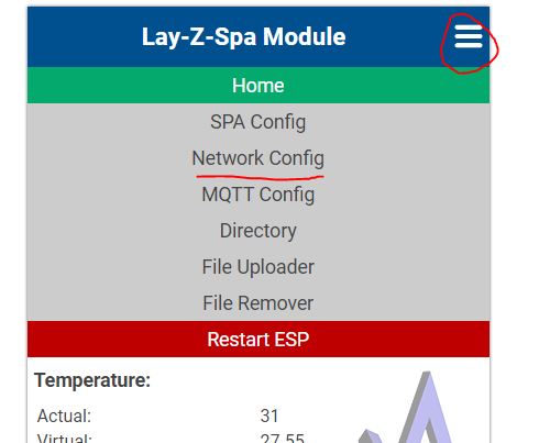
Here you can set up your home Wi-Fi network. So that it will always connect and be accessible from your home network. Enter the SSID and password of your network and click save. Shortly it should be connected to your network. We can leave everything else as is for now and continue with the installation of the module to the pump.
Now we solder the connector cables. Here is the diagram of how the wiring should fit.
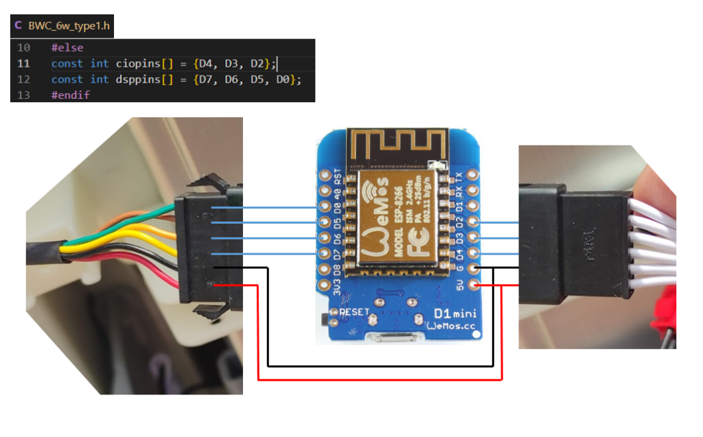
Solder the wires as shown in the above diagram. We won’t be using the one wire on the white-colored wire connector as it is not needed since it is used for the audio sound when turning on. Once installed we will get this little jingle that plays whenever you turn on the hot tub.
You should have something like this once done with one female and one male connector coming from the board.
Not my exact picture but taken from the GitHub page as an example. Now plug both the connectors into the two plugs that we disconnected which connect the display to the pump. This WeMos board will sit in between them and act as the bridge and controller.

Without assembling everything back we can test if it works. Place the top cover with the wiring and board inside somewhere in an empty space. Plug the power in and turn on the pump. If everything went well you should hear a jingle. The display will scroll some text informing you of the current version and show the IP address too. It will then display as normal showing the temperature. Now we can test if the remote control works or not.
Go into the web interface and you should have controls ready to test.
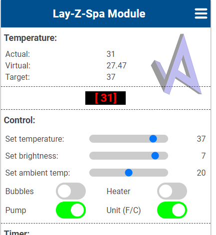
Since when I tested the board was not connected to the tub and there was no water I avoided testing the Heater and Pump functions. I just tested if setting the temperature and activating the Bubbles works. So if you were able to turn on the Bubbles and the pump started blowing air congratulations you should have everything working. Setting the temperature up or down should reflect on the display as well. We’re done! Now all that is left is to assemble the top cover back with the 6 screws. If you are worried about the board getting wet (not that I found any water inside the pump) You might want to cover it with something or have a case for it. You can of course 3D Print one for yourself. There are many models on Thingiverse like this https://www.thingiverse.com/thing:2045664
Conclusion
That is pretty much all there is to do. Once assembled you can place it back on your hot tub and check all the other functions. Also, be aware of your Wi-Fi reception if the hot tub is far from your router it might not reach to connect so check if there is good connectivity. For additional functions, it supports MQTT so you can add the Lay-Z-Spa to something like Home Assistant for automation and control. For more information on the features, model support, issues and support go to the GitHub link https://github.com/visualapproach. The community is quite active and healthy there and can help you out.
I hope this has helped you and provided some fun functionality.


Bought a board from Amazon (https://www.amazon.com.be/-/en/dp/B01N9RXGHY?ref=ppx_yo2ov_dt_b_fed_asin_title&th=1) that is looking to me as almost exactly as what is mentioned in the guide.
Code part went smooth (very easy) and when connected to USB, i could access the webinterface, even via home wifi.
Soldered the wires according to the new diagram, triple checked all connections to correct spots.
When installing it in the pump and powering it on, there is no “beep” which means power is not going to the display 🙁
Redid the “2 into 1” connection for 5V but no difference.
I guess it was worth a shot but unfortunately not working 🙁
If anybody has any tips, feel free 🙂
Hi antanaitis,
Thanks for this , is it also working for esp32 ?
Its hard to find nowadays d1 mini v2 esp8266
Br Hans
Hi,
There are some discussion regarding esp32 so you may need to read up on it here in the threads if its possible. https://github.com/visualapproach/WiFi-remote-for-Bestway-Lay-Z-SPA/discussions?discussions_q=esp32
Regarding the V2 versions they do exist still but they are more scarce so I would confirm with any seller before buying or try any local places you might have that sells these boards to confirm in person.
Thanks for this guide and the updates! First had some soldering trouble but got everything up and running…
Glad you got it working! Have fun!
I need some help, I have soldered headers to my wemos and put dupont pins on my wires. I have my wemos connected to 5v and ground, can access the web interface but the abc status never changes so it’s never reading any data.
It was like this when I wired everything with the display and the display was blank so I’m trying to start with just the pump side.
My wiring in order goes
Yellow
White
Blue
Red
Green
Black
Connecting to the pump connector makes yellow 5v and white ground, so going off the data on this guide.
Blue = D4
Red = D3
Green = D2
depending on your soldered pinout, you may need to just adjust the pinout in the webui under hardware config since you can access the interface.
Hi,
May I ask how you did update the software? Do you have to uninstall the D1 Mini from the pump or can you do it OTA?
Thanks,
Gerwin
Hi,
Was super happy with the spa the whole summer, thanks to your guide! Now it’s time to put in storage and wanted to update the firmware first (mainly because the ” time to ready” doesn’t work in MQTT in the version I use now.
However I am running into a little trouble updating the firmware to the latest. is it possible to update OTA?
Is it correct to just open the directory. Then in platformIO comment the esptool and uncomment the lines with upload protocol, upload port, flags en authentication.
Then with the little arrow (upload) and that’s it? Do I need to upload the other files too?
Or did you uninstall the d1 mini from the pump and connected via USB?
Thanks!
Gerwin
Hi,
No OTA does not work in this case since we are changing the default board config to the d1_mini and use a custom pin out. As far as the wiki on the github page states that OTA is not possible and I think I even seen users with the compatible boards having issues with OTA. In any case unless there are some worthwhile features in the update, then if everything already works for you. I would recommend just staying on the version you are at now. Since I only updated due to other users having issue to check if something changed. But I didn’t discover anything notable in the newest version that would be interesting to check out. But to answer your question – yes I have to pull out and connect the board to my computer to update it.
Thanks for your reply. There seems to be one little thing in the newest software that is interesting for me. Via MQTT the “time to ready” value seems to be not correct (at least in home assistant I do not get the correct value) and that seems to be fixed in the newer releases.
little bit scared to pull it out and reinstall the software as it works so beautifully now. Now I now what to do. Thanks!
Thanks, it was the first time for me to build something with a processorboard like this (Wemos M1 miniboard) but it is easy to do and very flexible. I will use them more often in the future for domotica projects.
Did you ever consider to make the powerconsumption adjustable? It would be interested to bring the heating in line with my solar overproduction.
i did see that the heating module has 2 inputs (probabely 2 x 1000W) but are switched with relays. Anyway i will think about it myself also.
I buyed you a coffee, sorry only for this month
Hey, thank you for the reply and support! It should be possible with integrating it with some form of automation system. In my case I’ve done it with Home Assistant as I wrote in this post:
https://antanaitis.lt/2023/09/13/home-assistant-hot-tub-integration/
In general this can be configured using MQTT . So it’s definitely possible to integrate with a plethora of systems/integrations that supports this. In this way you could automate control of when the pump should start and stop heating based on the solar production if you have it monitored through a system as well.
Hello,
Thank you for the guide!
I’m in the middle of doing it myself, but the soldering/wiring diagram is quite unclear, because the photo of the soldered wires are completely the opposite of the wiring diagram. The colors are random, and the male/female connectors are also swapped when I compare the two.
I did it based on the photo, because that’s “real”, the other one is just a virtual diagram, but it would be nice to fix it / clear it up in the guide.
It would be also nice to point out that once you modify the pinout (CIO and DSP), you’ll no longer be able to connect it with your USB cable to your PC (at least, I couldn’t, it lost the blue signal light and the website became unavailable immediately).
I’ll try connect it in a few hours to the pump, and we’ll see if it works.
Hey! Thanks for the comment. Regarding the wiring unfortunately this is a problem on my end since the wiring that comes from the pump which then connects to the display of the unit had actually swapped wire colors on the connection. So in my case I think this is some manufacturing mistake. While it works the colors do indeed not match which will probably not be the case for you. In regards to clearer photos you can actually find more of the same board people have uploaded here:
https://github.com/visualapproach/WiFi-remote-for-Bestway-Lay-Z-SPA/discussions/312
Regarding the connection issue. Actually I did not experience it or I don’t recall having such an issue. I’ve had to pull the board out once or twice to update it a year or two ago and had no issues connecting it I believe. I checked the manual on the GitHub page and it also doesn’t mention anything of the sort. Maybe its just a pin out configuration issue and it is shorting to the USB connector causing it to not boot as you mentioned “it lost the blue signal light and the website became unavailable immediately”. But that’s just a guess, I’d suggest to just go over and recheck everything.
Hope this was helpful in some way!
Thank you for your quick reply!
I managed to install it in my pump, but first it made the behavior of physical buttons on the pump really weird. Like pressing “bubbles” would turn on the heater, and things like that. I opened an issue on github, they suggested I add a level shifter, so I did that. Now it seems to be much better, although still very far from perfect. There’s a significant delay between the pressing of the button and the action it does (like changing the temperate, turning on/off bubbles, etc). I made some photos and videos of what I experience below:
https://photos.app.goo.gl/361u4MMUxvUqnzPK8
I also made a video of how it works without the PCB installed, just for comparison. That kind of fast responsivity is now gone. Not sure if that’s normal.
I’m not sure if this is the best it can do, or if I messed up anything…?
Hey, thanks for the update. Based on the photos of the board. The only thing I’m not sure of is why the 3v3 pin is wired to something on your board. Hard to tell where it goes. But based on the provided wiring example you should have the pins wired with D0, D5, D6, D7 on one side of the board and the other side should have D2, D3, D4 and the exception being that both the Ground and 5V has wires coming from both connectors. That 3v3 and 5v both being wired might be the cause of the issue.
Hey,
The 3V3 pin is connected to the level shifters’ “low voltage”, or “LV” pin. Based on some research, it’s where it’s supposed to go, when someone is using level shifters. The idea is that the level shifter scales down the 5V signals coming from the pump to 3V3 before it arrives on the PCB, and vica versa: it amplified the 3v3 signals to 5V output signals. And for that, we need both the 5V, and the 3V3 pins.
Do your buttons on your pump work better/faster than mine on the video?
So I pulled the pump out of storage and updated it to the latest version. I was thinking perhaps there was some code changes that changed the behavior. But after updating to v4.4.8 I do not experience the issues you described. I added an update to the top of the post here and uploaded a hopefully more clearer connection visual of what wire connects to which end and pin. In my case I am not using any level shifters and the display buttons when pressed are quick and snappy which I tested on both the previous v4.1.3 and the v4.4.8 version with no difference. The only thing I can suggest here is to re-check the wiring and solder joints that the connections are correct and proper as it seems everything has remained the same. Also to note the white cables coming from the pump being white, they do have red markings on them that can be identified as each is marked differently by lines, dots, x’s etc. So that could be also a good reference of which wire goes where as it should be visible in my updated image.
Hello
Great work, seems way more simple than the initial version.
i’m living in France and I cannot find the wemos D1 mini v2.2.0… There is a ton offre website selling some kinds of D1 mini but it’s impossible to know for sure the version.
Do you have any tips or links?
Thanks for your help!
Hi, did you manage to find it out? I’m encountering the same situation as you.
Thank you!
There is this one that I might order that is marked as v2:
https://fr.aliexpress.com/item/1005007877904928.html
I hope that the good version
This one works 😉 I just installed it ! We will see if it lasts long
Or this one
https://www.otronic.nl/fr/esp8266-d1-mini-v2-wi-fi-carte-de-developpement-ch.html
Glad you did find one. For other readers to make life more easy: you should search for the D1 mini with micro USB
You should be able to find those. The USB-C ones didn’t work for me. So probably that’s one of the main differences between v2 and v3/pro